OPERATION | ||
|
|
|
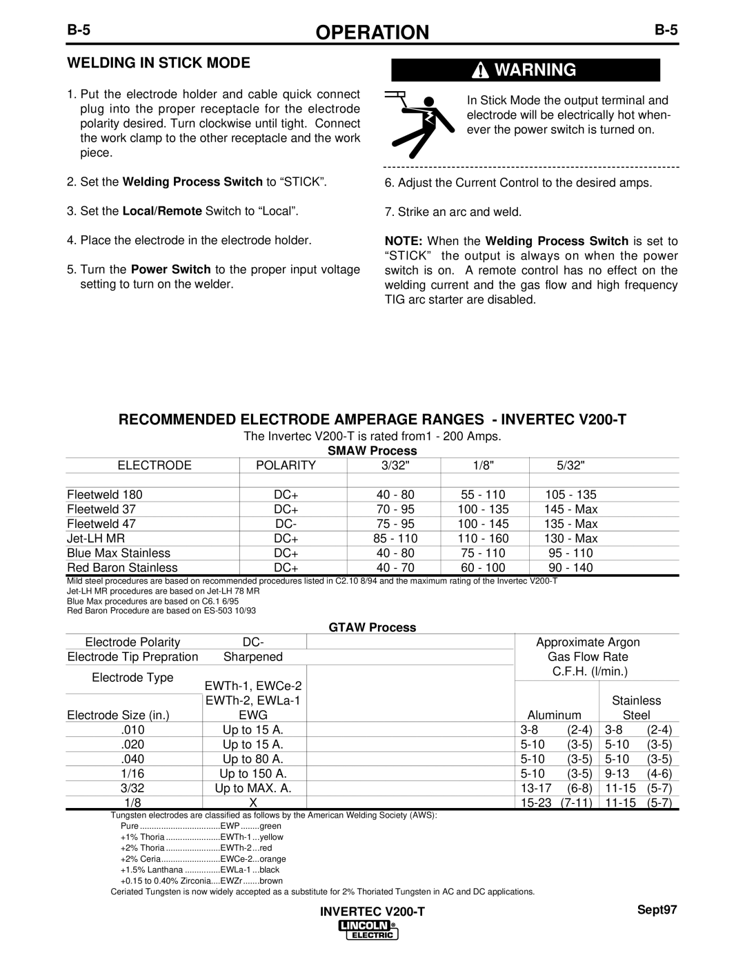
WELDING IN STICK MODE
1.Put the electrode holder and cable quick connect plug into the proper receptacle for the electrode polarity desired. Turn clockwise until tight. Connect the work clamp to the other receptacle and the work piece.
2.Set the Welding Process Switch to “STICK”.
3.Set the Local/Remote Switch to “Local”.
4.Place the electrode in the electrode holder.
5.Turn the Power Switch to the proper input voltage setting to turn on the welder.
![]() WARNING
WARNING
In Stick Mode the output terminal and electrode will be electrically hot when- ever the power switch is turned on.
6.Adjust the Current Control to the desired amps.
7.Strike an arc and weld.
NOTE: When the Welding Process Switch is set to “STICK” the output is always on when the power switch is on. A remote control has no effect on the welding current and the gas flow and high frequency TIG arc starter are disabled.
RECOMMENDED ELECTRODE AMPERAGE RANGES - INVERTEC V200-T
The Invertec
SMAW Process
ELECTRODE |
| POLARITY |
| 3/32" | 1/8" |
|
|
|
| 5/32" |
|
| |||
|
|
|
|
|
|
|
|
|
|
|
|
|
|
|
|
Fleetweld 180 |
|
| DC+ |
| 40 - 80 | 55 - 110 |
|
|
| 105 - 135 |
|
| |||
Fleetweld 37 |
|
| DC+ |
| 70 - 95 | 100 - 135 |
|
|
| 145 - Max |
|
| |||
Fleetweld 47 |
|
| DC- |
| 75 - 95 | 100 - 145 |
|
|
| 135 - Max |
|
| |||
|
| DC+ |
| 85 - 110 | 110 - 160 |
|
|
| 130 - Max |
|
| ||||
Blue Max Stainless |
|
| DC+ |
| 40 - 80 | 75 - 110 |
|
|
| 95 - 110 |
|
| |||
Red Baron Stainless |
|
| DC+ |
| 40 - 70 | 60 - 100 |
|
|
| 90 - 140 |
|
| |||
Mild steel procedures are based on recommended procedures listed in C2.10 8/94 and the maximum rating of the Invertec |
|
| |||||||||||||
|
|
|
|
|
|
|
|
|
|
|
| ||||
Blue Max procedures are based on C6.1 6/95 |
|
|
|
|
|
|
|
|
|
|
|
| |||
Red Baron Procedure are based on |
|
|
|
|
|
|
|
|
|
|
|
| |||
|
|
|
|
|
| GTAW Process |
|
|
|
|
|
|
|
| |
Electrode Polarity |
| DC- |
|
|
|
|
|
| Approximate Argon |
| |||||
Electrode Tip Prepration | Sharpened |
|
|
|
|
|
| Gas Flow Rate |
| ||||||
Electrode Type |
|
|
|
|
|
|
|
|
|
|
| C.F.H. (l/min.) |
| ||
|
|
|
|
|
|
|
|
|
|
|
|
|
| ||
|
|
|
|
|
|
|
|
|
|
|
| ||||
|
|
|
|
|
|
|
|
|
| Stainless | |||||
Electrode Size (in.) |
| EWG |
|
|
|
|
| Aluminum | Steel | ||||||
.010 |
| Up to 15 A. |
|
|
|
|
| ||||||||
.020 |
| Up to 15 A. |
|
|
|
| |||||||||
.040 |
| Up to 80 A. |
|
|
|
| |||||||||
1/16 |
| Up to 150 A. |
|
|
|
| |||||||||
3/32 |
| Up to MAX. A. |
|
|
|
| |||||||||
1/8 |
|
| X |
|
|
|
|
| |||||||
Tungsten electrodes are classified as follows by the American Welding Society (AWS): |
|
|
|
|
|
|
|
| |||||||
Pure | EWP | green |
|
|
|
|
|
|
|
|
|
| |||
+1% Thoria | yellow |
|
|
|
|
|
|
|
|
|
| ||||
+2% Thoria | red |
|
|
|
|
|
|
|
|
|
| ||||
+2% Ceria | orange |
|
|
|
|
|
|
|
|
|
| ||||
+1.5% Lanthana | black |
|
|
|
|
|
|
|
|
|
| ||||
+0.15 to 0.40% Zirconia.... | EWZr | brown |
|
|
|
|
|
|
|
|
|
| |||
Ceriated Tungsten is now widely accepted as a substitute for 2% Thoriated Tungsten in AC and DC applications.
INVERTEC | Sept97 |