OPERATION | ||
|
|
|
EXPLANATION OF 2 STEP AND 4 STEP MODES
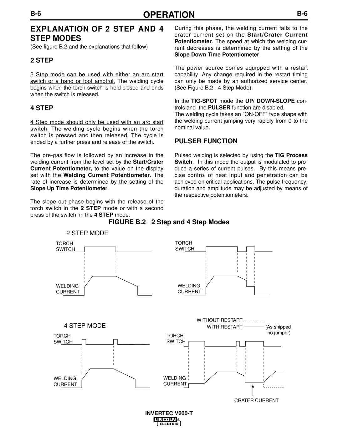
(See figure B.2 and the explanations that follow)
2 STEP
2 Step mode can be used with either an arc start switch or a hand or foot amptrol. The welding cycle begins when the torch switch is held closed and ends when the switch is released.
4 STEP
4 Step mode should only be used with an arc start switch. The welding cycle begins when the torch switch is pressed and then released. The cycle is ended by a further press and release of the switch.
The
The slope out phase begins with the release of the torch switch in the 2 STEP mode or with a second press of the switch in the 4 STEP mode.
During this phase, the welding current falls to the crater current set on the Start/Crater Current Potentiometer. The speed at which the welding cur- rent decreases is determined by the setting of the Slope Down Time Potentiometer.
The power source comes equipped with a restart capability. Any change required in the restart timing can only be made by an authorized service center. (See Figure B.2 - 4 Step Mode).
In the
The welding cycle takes an
PULSER FUNCTION
Pulsed welding is selected by using the TIG Process Switch. In this mode the output is modulated to pro- duce a series of current pulses. By this means pre- cise control of heat input and penetration can be achieved on critical applications. The pulse frequency, duration and amplitude may be adjusted by means of the respective potentiometers.
FIGURE B.2 2 Step and 4 Step Modes
2 STEP MODE
TORCH
SWITCH
TORCH SWITCH
WELDING | WELDING |
CURRENT | CURRENT |
WITHOUT RESTART
4 STEP MODE
TORCH
SWITCH
WITH RESTART |
| (As shipped | |
| |||
TORCH | no jumper) | ||
|
| ||
SWITCH |
|
| |
|
| ||
|
|
|
|
WELDING | WELDING |
CURRENT | CURRENT |
CRATER CURRENT
INVERTEC