PBUS Accessories
Several accessories (keypads, proximity readers, remote receivers) can be connected to the
Linear’s PBUS devices compatible with the
•
•
•
•
•
1. Mount and install the accessory as described in its installation |
instructions. |
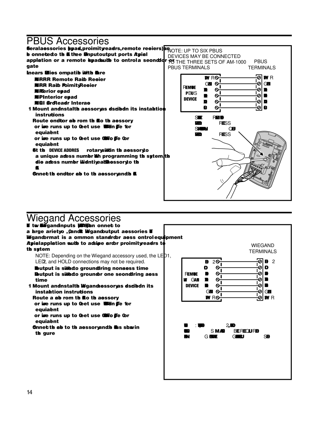
NOTE: UP TO SIX PBUS DEVICES MAY BE CONNECTED TO THE THREE SETS OF
PBUS TERMINALS
PWR ![]()
![]()
GND ![]()
![]()
REMOTE DAT1 ![]()
![]()
PBUS
DAT0
DEVICE
DVAL ![]()
![]()
PCLK ![]()
![]()
PBUS
TERMINALS
PWR
GND
DAT1
DAT0
DVAL
PCLK
2. Route |
•For wire runs up to 300 feet use 24 AWG Belden Type 9931 or equivalent.
•For wire runs up to 600 feet use 20 AWG Weico Type 9405 or equivalent.
3.Set the DEVICE ADDRESS rotary switch in the accessory to a unique address number. When programming the system, the device address number will identify each PBUS accessory to the
4.Connect the
SET THE REMOTE DEVICE ADDRESS SWITCH TO A UNIQUE DEVICE ADDRESS
Wiegand Accessories
The two
✦NOTE: Depending on the Wiegand accessory used, the LED1, LED2, and HOLD connections may not be required.
•LED1 output is switched to ground during
•LED2 output is switched to ground for one second during access
time.
1.Mount and install the Wiegand accessory as described in its installation instructions.
2.Route a cable from the
•For wire runs up to 300 feet use 24 AWG Belden Type 9931 or equivalent.
•For wire runs up to 500 feet use 20 AWG Weico Type 9405 or equivalent.
LED2 ![]()
![]()
HOLD ![]()
![]() REMOTE LED1
REMOTE LED1 ![]()
![]() WIEGAND DAT1
WIEGAND DAT1 ![]()
![]() DEVICE DAT0
DEVICE DAT0 ![]()
![]() GND
GND ![]()
![]() PWR
PWR ![]()
![]()
WIEGAND
TERMINALS
LED2
HOLD
LED1
DAT1
DAT0
GND
PWR
3.Connect the cable to the accessory and the
NOTE: THE LED1, LED2, AND HOLD CONNECTIONS MAY NOT BE REQUIRED DEPENDING ON THE WIEGAND DEVICE USED
14