Optional Postal Lock
A postal lock can be installed in the
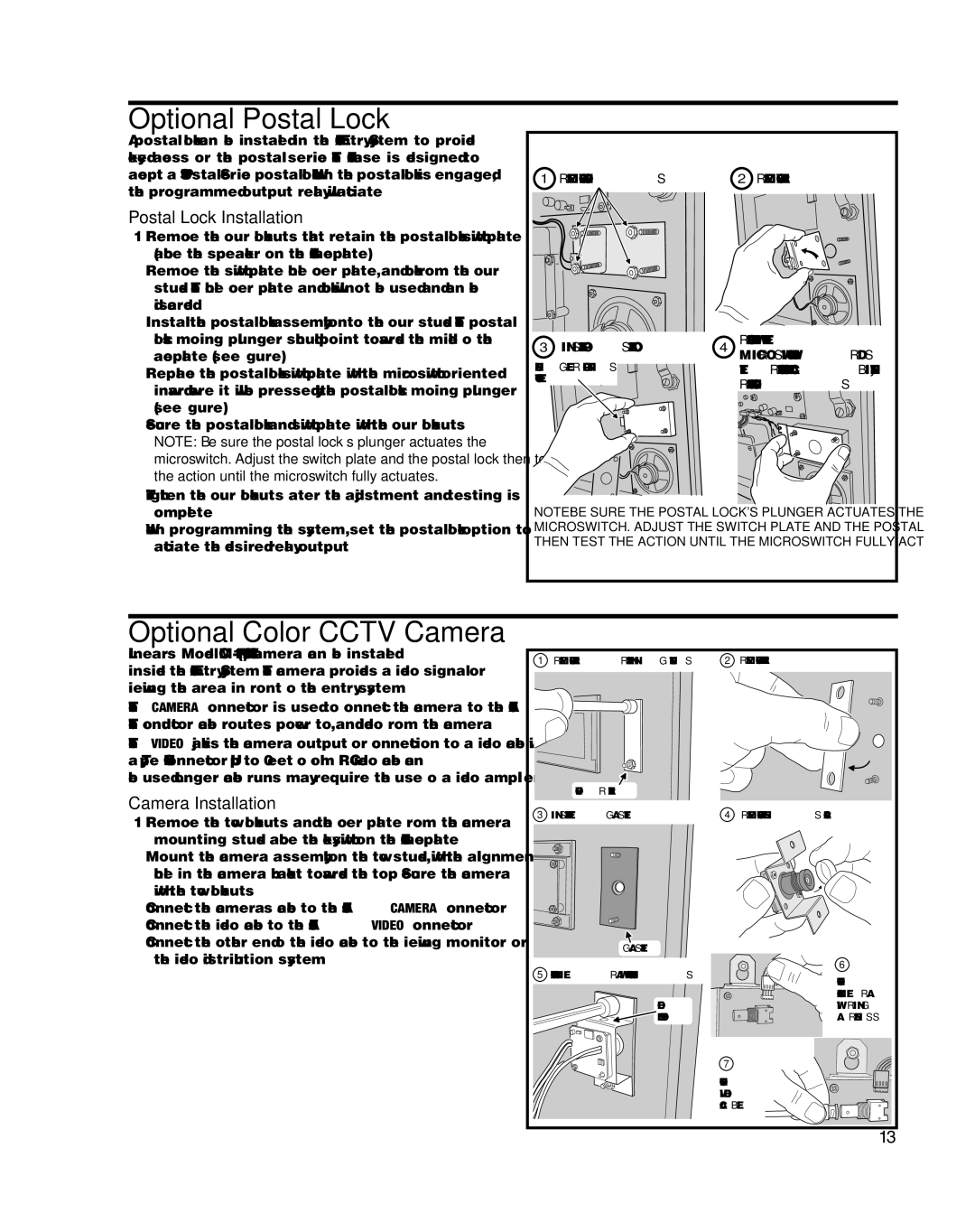
Postal Lock Installation
1.Remove the four locknuts that retain the postal lock switch plate (above the speaker on the
2.Remove the switch plate hole cover plate, and block from the four studs. The hole cover plate and block will not be used and can be discarded.
3.Install the postal lock assembly onto the four studs. The postal lock’s moving plunger should point towards the middle of the faceplate (see fi gure).
4.Replace the postal lock switch plate with the microswitch oriented inward where it will be pressed by the postal lock’s moving plunger (see fi gure).
5.Secure the postal lock and switch plate with the four locknuts.
✦NOTE: Be sure the postal lock’s plunger actuates the microswitch. Adjust the switch plate and the postal lock then test the action until the microswitch fully actuates.
1REMOVE LOCKNUTS
3INSTALL POSTAL LOCK
PLUNGER POINTS
TO LEFT
2REMOVE PLATE
4REPLACE PLATE WITH THE MICROSWITCH TOWARDS THE FRONT OF THE CABINET, REPLACE LOCKNUTS
6.Tighten the four locknuts after the adjustment and testing is complete.
7.When programming the system, set the postal lock option to activate the desired relay output.
NOTE: BE SURE THE POSTAL LOCK'S PLUNGER ACTUATES THE MICROSWITCH. ADJUST THE SWITCH PLATE AND THE POSTAL LOCK THEN TEST THE ACTION UNTIL THE MICROSWITCH FULLY ACTUATES
Optional Color CCTV Camera
Linear’s Model
The CAMERA connector is used to connect the camera to the
Camera Installation
1.Remove the two locknuts and the cover plate from the camera mounting studs above the keyswitch on the
2.Mount the camera assembly on the two studs, with the alignment hole in the camera bracket towards the top. Secure the camera with the two locknuts.
3.Connect the camera’s cable to the
4.Connect the video cable to the
5.Connect the other end of the video cable to the viewing monitor or the video distribution system.
1 REMOVE PLATE RETAINING NUTS | 2 REMOVE THE PLATE |
COVER PLATE
3 INSTALL THE GASKET | 4 REMOVE THE LENS CAP |
GASKET |
| |
5 ATTACH CAMERA WITH TWO NUTS | 6 | |
CONNECT | ||
| ||
| CAMERA | |
HOLE | WIRING | |
ON TOP | HARNESS | |
| 7 | |
| CONNECT | |
| VIDEO | |
| CABLE |
13