Relay Output Wiring
Any of the four relay outputs channels
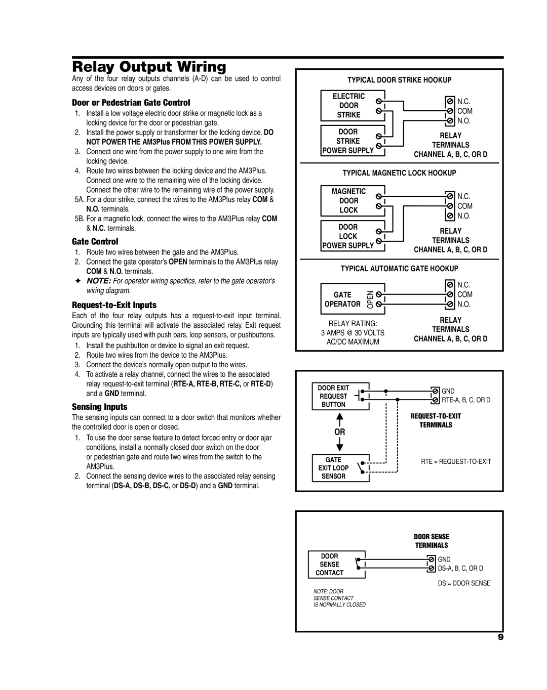
TYPICAL DOOR STRIKE HOOKUP
Door or Pedestrian Gate Control
1. | Install a low voltage electric door strike or magnetic lock as a |
| locking device for the door or pedestrian gate. |
2. | Install the power supply or transformer for the locking device. DO |
| NOT POWER THE AM3Plus FROM THIS POWER SUPPLY. |
3. | Connect one wire from the power supply to one wire from the |
| locking device. |
ELECTRIC
DOOR
STRIKE
DOOR
STRIKE
POWER SUPPLY
N.C.
COM
N.O.
RELAY
TERMINALS
CHANNEL A, B, C, OR D
4. Route two wires between the locking device and the AM3Plus. |
Connect one wire to the remaining wire of the locking device. |
TYPICAL MAGNETIC LOCK HOOKUP
Connect the other wire to the remaining wire of the power supply. |
5A. For a door strike, connect the wires to the AM3Plus relay COM & N.O. terminals.
5B. For a magnetic lock, connect the wires to the AM3Plus relay COM & N.C. terminals.
Gate Control
1. | Route two wires between the gate and the AM3Plus. |
2. | Connect the gate operator’s OPEN terminals to the AM3Plus relay |
MAGNETIC
DOOR
LOCK
DOOR
LOCK
POWER SUPPLY
N.C.
COM
N.O.
RELAY
TERMINALS
CHANNEL A, B, C, OR D
COM & N.O. terminals. |
✦NOTE: For operator wiring specifics, refer to the gate operator’s wiring diagram.
Request-to-Exit Inputs
Each of the four relay outputs has a
1.Install the pushbutton or device to signal an exit request.
2.Route two wires from the device to the AM3Plus.
3.Connect the device’s normally open output to the wires.
4.To activate a relay channel, connect the wires to the associated relay
Sensing Inputs
The sensing inputs can connect to a door switch that monitors whether the controlled door is open or closed.
1.To use the door sense feature to detect forced entry or door ajar conditions, install a normally closed door switch on the door
or pedestrian gate and route two wires from the switch to the AM3Plus.
2.Connect the sensing device wires to the associated relay sensing terminal
TYPICAL AUTOMATIC GATE HOOKUP
|
|
|
|
| N.C. |
GATE |
|
|
|
| |
|
|
|
| COM | |
OPERATOR OPEN |
|
|
|
| N.O. |
|
|
| |||
|
|
|
| ||
|
|
|
| ||
RELAY RATING: |
| RELAY | |||
| TERMINALS | ||||
3 AMPS @ 30 VOLTS |
| ||||
| CHANNEL A, B, C, OR D | ||||
AC/DC MAXIMUM |
| ||||
|
|
|
| ||
DOOR EXIT |
|
|
|
|
|
|
|
|
|
| GND | ||
REQUEST |
|
|
|
|
|
|
|
|
|
|
| ||
|
|
|
|
|
|
|
| ||||||
BUTTON |
|
|
| ||||||||||
|
|
|
|
|
|
|
|
| |||||
|
|
|
|
|
|
| |||||||
|
|
|
|
|
|
|
|
| TERMINALS | ||||
OR |
| ||||||||||||
|
|
|
|
|
|
|
| ||||||
GATE |
|
| RTE = |
|
|
EXIT LOOP
SENSOR
|
|
|
| DOOR SENSE | ||||
|
|
|
| TERMINALS | ||||
|
|
|
|
|
|
|
|
|
DOOR |
|
|
|
|
|
|
| GND |
SENSE |
|
|
|
|
|
|
| |
|
|
|
|
| ||||
CONTACT |
|
|
|
|
|
| ||
|
|
|
|
|
| DS = DOOR SENSE | ||
|
|
|
|
|
|
|
| |
NOTE: DOOR |
|
|
|
|
|
| ||
SENSE CONTACT |
|
|
|
|
|
| ||
IS NORMALLY CLOSED |
|
|
|
|
|
| ||
9