MODEL
MODEL
Ref. | Part |
|
| Ref. |
| Part |
|
|
No. | Number | Description |
| No. |
| Number | Description | |
|
|
|
|
|
|
|
|
|
2 | Welded Cabinet Assembly | 38 | Limit Switch | |||||
3 | Enclosure Door | 40 | Screw, #6 - 32 x 2 1/4”, | |||||
5 | Lock Assembly with Key | 42 | Keps Nut, | |||||
6 | Bearing Block Assembly Kit | 43 | Limit Cam | |||||
7 | Drive Shaft Assembly | 50 | Key, 3/16” x 3/16” x 1 1/4” | |||||
8 | Gate Arm Flange | 51 | Key, Intermediate Shaft | |||||
9 | Arm Attachment Channel | 55 | Thrust Washer | |||||
10 | Counterweight | 56 | Shoulder Bolt, 1/2” - 32 x 2” | |||||
12 | Connecting Link with Bearings | 60 | Bearing, Pillow Block | |||||
26 | Flange Bearings | 61 | Key, Intermediate Shaft | |||||
17 | Motor 24 VDC | 71 | Transformer Assembly | |||||
| Brush Replacement Kit |
| Bridge Rectifier | |||||
| Motor Mounting Bracket (not shown) |
| Diode | |||||
|
|
|
|
| Transformer only, 115/24V, 250VA | |||
18 | Intermediate Shaft |
| Fuse Holder | |||||
19 | Reducer and Crank Arm assembly |
| Fuse, 6A | |||||
21 | Reducer Pulley, 7” (2 required) | 72 | Power Box Mounting Plate | |||||
22 | Intermediate Pulley, 2” (2 required) | |||||||
23 | 73 | Power On/Off Switch Assembly | ||||||
24 | Motor Pulley, 1 5/8” |
| Switch only (20 Amp) | |||||
25 | Intermediate Pulley, 6” | 74 | Front Accessory Shelf | |||||
28 | ||||||||
29 | Carriage Bolt, | 76 | Battery Assembly | |||||
30 | Hex Nut, 3/8” | |||||||
31 | Flat Washer, 3/8” |
|
|
| (LINEAR supplied - some distributors | |||
32 | Wing Nut, |
|
|
| supply other batteries) | |||
33 | Set Collar, 1 1/4” |
| Battery, 12V (2 required) | |||||
34 | Roll Pin, 3/8” x 1” x 2” |
| Velcro Tape, per foot | |||||
35 | Star Washer, #10 |
|
|
|
|
| ||
36 | Hex Nut, | *Specify color and texture. |
|
| ||||
37 | Screw, #8 - 32 x 3/8”, |
|
| |||||
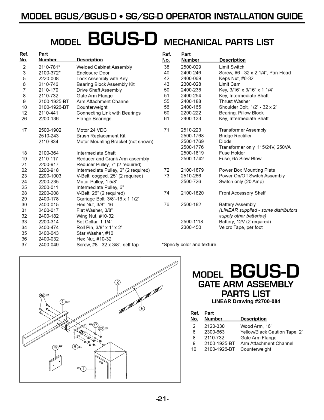
MODEL BGUS-D
GATE ARM ASSEMBLY
PARTS LIST
LINEAR Drawing #2700-084
Ref. | Part |
|
|
No. | Number | Description |
|
2 | Wood Arm, 16’ | ||
6 | Yellow/Black Caution Tape, 2” | ||
8 | Gate Arm Flange | ||
9 | Arm Attachment Channel | ||
10 | Counterweight | ||