MODEL
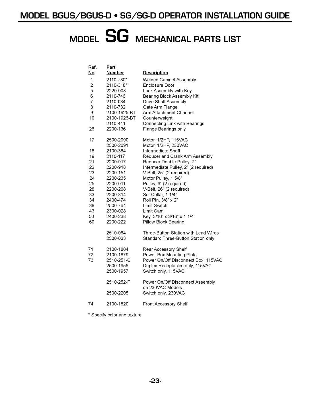
MODEL SG MECHANICAL PARTS LIST
Ref. | Part |
|
No. | Number | Description |
1 | Welded Cabinet Assembly | |
2 | Enclosure Door | |
5 | Lock Assembly with Key | |
6 | Bearing Block Assembly Kit | |
7 | Drive Shaft Assembly | |
8 | Gate Arm Flange | |
9 | Arm Attachment Channel | |
10 | Counterweight | |
| Connecting Link with Bearings | |
26 | Flange Bearings only | |
17 | Motor, 1/2HP, 115VAC | |
| Motor, 1/2HP, 230VAC | |
18 | Intermediate Shaft | |
19 | Reducer and Crank Arm Assembly | |
21 | Reducer Double Pulley, 7” | |
22 | Intermediate Pulley, 2” (2 required) | |
23 | ||
24 | Motor Pulley, 1 5/8” | |
25 | Pulley, 6” (2 required) | |
28 | ||
33 | Set Collar, 1 1/4” | |
34 | Roll Pin, 3/8” x 2” | |
38 | Limit Switch | |
43 | Limit Cam | |
50 | Key, 3/16” x 3/16” x 1 1/4” | |
60 | Pillow Block Bearing | |
| ||
| Standard |
71
72
73
| Power On/Off Disconnect Assembly | |
|
| on 230VAC Models |
| Switch only, 230VAC | |
74 | Front Accessory Shelf |
* Specify color and texture
