MODEL
CONTROL BOARD ADJUSTMENTS
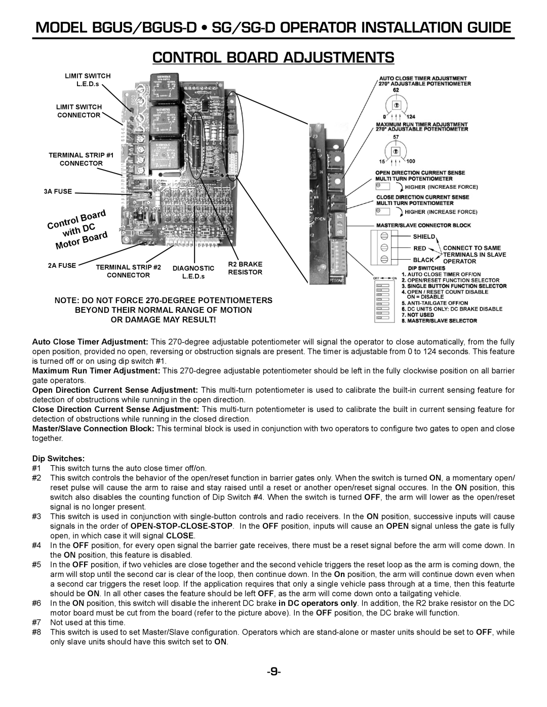
LIMIT SWITCH
L.E.D.s
LIMIT SWITCH
CONNECTOR ![]()
TERMINAL STRIP #1
CONNECTOR
3A FUSE |
|
|
|
|
Board |
|
|
| |
|
|
| ||
Control | DC |
|
|
|
with |
|
|
| |
Board |
|
|
| |
Motor |
|
|
| |
|
|
|
| |
2A FUSE | TERMINAL STRIP #2 |
|
| R2 BRAKE |
DIAGNOSTIC | ||||
| CONNECTOR | L.E.D.s | RESISTOR | |
|
| |||
NOTE: DO NOT FORCE
BEYOND THEIR NORMAL RANGE OF MOTION
OR DAMAGE MAY RESULT!
Auto Close Timer Adjustment: This
Maximum Run Timer Adjustment: This
Open Direction Current Sense Adjustment: This
Close Direction Current Sense Adjustment: This
Master/Slave Connection Block: This terminal block is used in conjunction with two operators to configure two gates to open and close together.
Dip Switches:
#1 This switch turns the auto close timer off/on.
#2 This switch controls the behavior of the open/reset function in barrier gates only. When the switch is turned ON, a momentary open/ reset pulse will cause the arm to raise and stay raised until a reset or another open/reset signal occures. In the ON position, this switch also disables the counting function of Dip Switch #4. When the switch is turned OFF, the arm will lower as the open/reset signal is no longer present.
#3 This switch is used in conjunction with
#4 In the OFF position, for every open signal the barrier gate receives, there must be a reset signal before the arm will come down. In the ON position, this feature is disabled.
#5 In the OFF position, if two vehicles are close together and the second vehicle triggers the reset loop as the arm is coming down, the arm will stop until the second car is clear of the loop, then continue down. In the On position, the arm will continue down even when a second car triggers the reset loop. If the application requires that only a single vehicle pass through at a time, then this featurte should be ON. In all other cases the feature should be left OFF, as the arm will come down onto a tailgating vehicle.
#6 In the ON position, this switch will disable the inherent DC brake in DC operators only. In addition, the R2 brake resistor on the DC motor board must be cut from the board (refer to the picture above). In the OFF position, the DC brake will function.
#7 Not used at this time.
#8 This switch is used to set Master/Slave configuration. Operators which are