Advanced Controller Programming (Cont.)
Reset Cycle Count
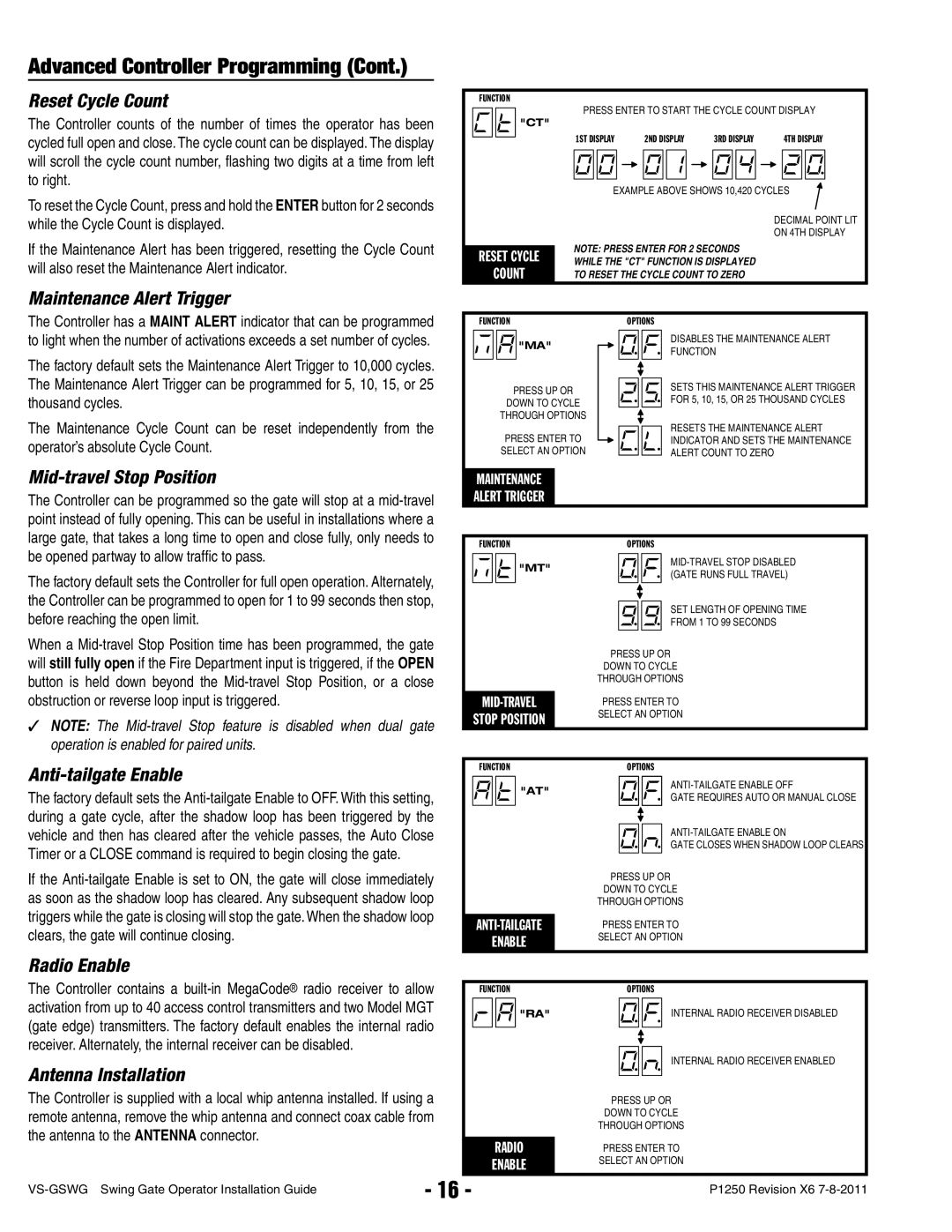
The Controller counts of the number of times the operator has been cycled full open and close. The cycle count can be displayed. The display will scroll the cycle count number, fl ashing two digits at a time from left to right.
To reset the Cycle Count, press and hold the ENTER button for 2 seconds while the Cycle Count is displayed.
If the Maintenance Alert has been triggered, resetting the Cycle Count will also reset the Maintenance Alert indicator.
Maintenance Alert Trigger
FUNCTION
![]() "CT"
"CT"
RESET CYCLE
COUNT
PRESS ENTER TO START THE CYCLE COUNT DISPLAY
1ST DISPLAY |
|
|
| 2ND DISPLAY |
|
|
| 3RD DISPLAY |
|
|
| 4TH DISPLAY | ||||||||
|
|
|
|
|
|
|
|
|
|
|
|
|
|
|
|
|
|
|
|
|
|
|
|
|
|
|
|
|
|
|
|
|
|
|
|
|
|
|
|
|
|
|
|
|
|
|
|
|
|
|
|
|
|
|
|
|
|
|
|
|
|
|
EXAMPLE ABOVE SHOWS 10,420 CYCLES
DECIMAL POINT LIT
ON 4TH DISPLAY
NOTE: PRESS ENTER FOR 2 SECONDS
WHILE THE "CT" FUNCTION IS DISPLAYED
TO RESET THE CYCLE COUNT TO ZERO
The Controller has a MAINT ALERT indicator that can be programmed to light when the number of activations exceeds a set number of cycles.
The factory default sets the Maintenance Alert Trigger to 10,000 cycles. The Maintenance Alert Trigger can be programmed for 5, 10, 15, or 25 thousand cycles.
The Maintenance Cycle Count can be reset independently from the operator’s absolute Cycle Count.
FUNCTION
![]()
![]()
![]()
![]() "MA"
"MA"
PRESS UP OR
DOWN TO CYCLE
THROUGH OPTIONS
PRESS ENTER TO SELECT AN OPTION
OPTIONS
DISABLES THE MAINTENANCE ALERT
FUNCTION
SETS THIS MAINTENANCE ALERT TRIGGER
FOR 5, 10, 15, OR 25 THOUSAND CYCLES
RESETS THE MAINTENANCE ALERT
INDICATOR AND SETS THE MAINTENANCE
ALERT COUNT TO ZERO
Mid-travel Stop Position
The Controller can be programmed so the gate will stop at a
The factory default sets the Controller for full open operation. Alternately, the Controller can be programmed to open for 1 to 99 seconds then stop, before reaching the open limit.
When a
✓NOTE: The
MAINTENANCE
ALERT TRIGGER
| FUNCTION |
| OPTIONS | |||||
|
|
|
| "MT" |
|
|
| |
|
|
|
|
|
|
| ||
|
|
|
|
|
|
| (GATE RUNS FULL TRAVEL) | |
|
|
|
|
|
|
|
| |
|
|
|
|
|
|
|
| SET LENGTH OF OPENING TIME |
|
|
|
|
|
|
|
| |
|
|
|
|
|
|
|
| |
|
|
|
|
|
|
|
| |
|
|
|
|
|
|
|
| FROM 1 TO 99 SECONDS |
|
|
|
|
|
|
|
|
|
|
|
|
|
| PRESS UP OR | |||
|
|
|
|
| DOWN TO CYCLE | |||
|
|
|
|
| THROUGH OPTIONS | |||
|
|
|
|
|
|
|
|
|
| PRESS ENTER TO | |||||||
| STOP POSITION | SELECT AN OPTION | ||||||
|
|
|
|
| ||||
Anti-tailgate Enable
The factory default sets the
If the
Radio Enable
FUNCTION
![]()
![]()
![]() "AT"
"AT"
ANTI-TAILGATE
ENABLE
OPTIONS
GATE REQUIRES AUTO OR MANUAL CLOSE
GATE CLOSES WHEN SHADOW LOOP CLEARS
PRESS UP OR
DOWN TO CYCLE
THROUGH OPTIONS
PRESS ENTER TO
SELECT AN OPTION
The Controller contains a
Antenna Installation
The Controller is supplied with a local whip antenna installed. If using a remote antenna, remove the whip antenna and connect coax cable from the antenna to the ANTENNA connector.
| FUNCTION |
| OPTIONS | |||||
|
|
|
| "RA" |
|
|
| INTERNAL RADIO RECEIVER DISABLED |
|
|
|
|
|
|
| ||
|
|
|
|
|
|
|
| INTERNAL RADIO RECEIVER ENABLED |
|
|
|
|
|
|
|
| |
|
|
|
|
|
|
|
| |
|
|
|
|
|
|
|
| |
|
|
|
|
|
|
|
| |
|
|
|
|
|
|
|
|
|
|
|
|
|
| PRESS UP OR | |||
|
|
|
|
| DOWN TO CYCLE | |||
|
|
|
|
| THROUGH OPTIONS | |||
|
|
|
|
|
|
|
|
|
|
| RADIO | PRESS ENTER TO | |||||
| ENABLE | SELECT AN OPTION | ||||||
|
|
|
|
| ||||
- 16 - | P1250 Revision X6 | |
|