Variable Speed Drive Programming
CAUTION
This unit has been programmed at the factory. No changes should be necessary for normal operation. PLEASE CONSULT THE FACTORY BEFORE MAKING ANY CHANGES!
Programming the Hitachi Inverter
1.Apply power
2.Press FUNC
3.Use ▲▼ arrows to advance to F_ _ (F002 for L200)
4.Press FUNC arrow to get to F02 (L100 ONLY)
5.Press FUNC, arrows to change to 3.0 (3.00 for L200),
STR
6.Up arrow to advance to next parameter, (F03), FUNC to view, arrows to change, STR to store and continue, advance through listed parameters and store new values.
7.To switch from one letter prefi x to another, press FUNC 3 times, advance to desired letter prefi x, press FUNC, advance to desired parameter.
8.When all parameters have been changed, advance to D01, press FUNC, then press STR. This will display the operating speed in Hz.
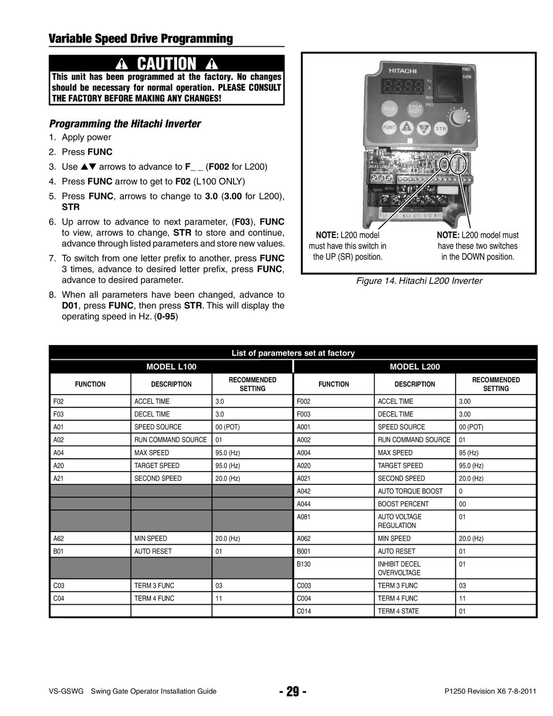
NOTE: L200 model | NOTE: L200 model must |
must have this switch in | have these two switches |
the UP (SR) position. | in the DOWN position. |
Figure 14. Hitachi L200 Inverter
List of parameters set at factory
MODEL L100
MODEL L200
FUNCTION | DESCRIPTION | RECOMMENDED | FUNCTION | DESCRIPTION |
| RECOMMENDED |
SETTING |
| SETTING | ||||
|
|
|
|
| ||
|
|
|
|
|
| |
F02 | ACCEL TIME | 3.0 | F002 | ACCEL TIME | 3.00 | |
|
|
|
|
|
| |
F03 | DECEL TIME | 3.0 | F003 | DECEL TIME | 3.00 | |
|
|
|
|
|
|
|
A01 | SPEED SOURCE | 00 (POT) | A001 | SPEED SOURCE | 00 | (POT) |
|
|
|
|
|
|
|
A02 | RUN COMMAND SOURCE | 01 | A002 | RUN COMMAND SOURCE | 01 |
|
|
|
|
|
|
|
|
A04 | MAX SPEED | 95.0 (Hz) | A004 | MAX SPEED | 95 | (Hz) |
|
|
|
|
|
| |
A20 | TARGET SPEED | 95.0 (Hz) | A020 | TARGET SPEED | 95.0 (Hz) | |
|
|
|
|
|
| |
A21 | SECOND SPEED | 20.0 (Hz) | A021 | SECOND SPEED | 20.0 (Hz) | |
|
|
|
|
|
|
|
|
|
| A042 | AUTO TORQUE BOOST | 0 |
|
|
|
|
|
|
|
|
|
|
| A044 | BOOST PERCENT | 00 |
|
|
|
|
|
|
|
|
|
|
| A081 | AUTO VOLTAGE | 01 |
|
|
|
|
| REGULATION |
|
|
|
|
|
|
|
| |
A62 | MIN SPEED | 20.0 (Hz) | A062 | MIN SPEED | 20.0 (Hz) | |
|
|
|
|
|
|
|
B01 | AUTO RESET | 01 | B001 | AUTO RESET | 01 |
|
|
|
|
|
|
|
|
|
|
| B130 | INHIBIT DECEL | 01 |
|
|
|
|
| OVERVOLTAGE |
|
|
|
|
|
|
|
|
|
C03 | TERM 3 FUNC | 03 | C003 | TERM 3 FUNC | 03 |
|
|
|
|
|
|
|
|
C04 | TERM 4 FUNC | 11 | C004 | TERM 4 FUNC | 11 |
|
|
|
|
|
|
|
|
|
|
| C014 | TERM 4 STATE | 01 |
|
|
|
|
|
|
|
|
- 29 - | P1250 Revision X6 | |
|