Operator Setup (cont.)
Open and Close Limit Adjustment
The limit nuts are not preset at the factory and must be adjusted for the gate in each installation.The limit switches are activated by two threaded nylon rotary limit nuts which are attached to a threaded limit shaft driven by a chain and sprockets from the main drive shaft. REMOVE THE CARDBOARD FILLER
BEFORE ADJUSTING THE LIMIT NUTS.
The Controller is factory setup for
CAUTION
If the operator is installed in a
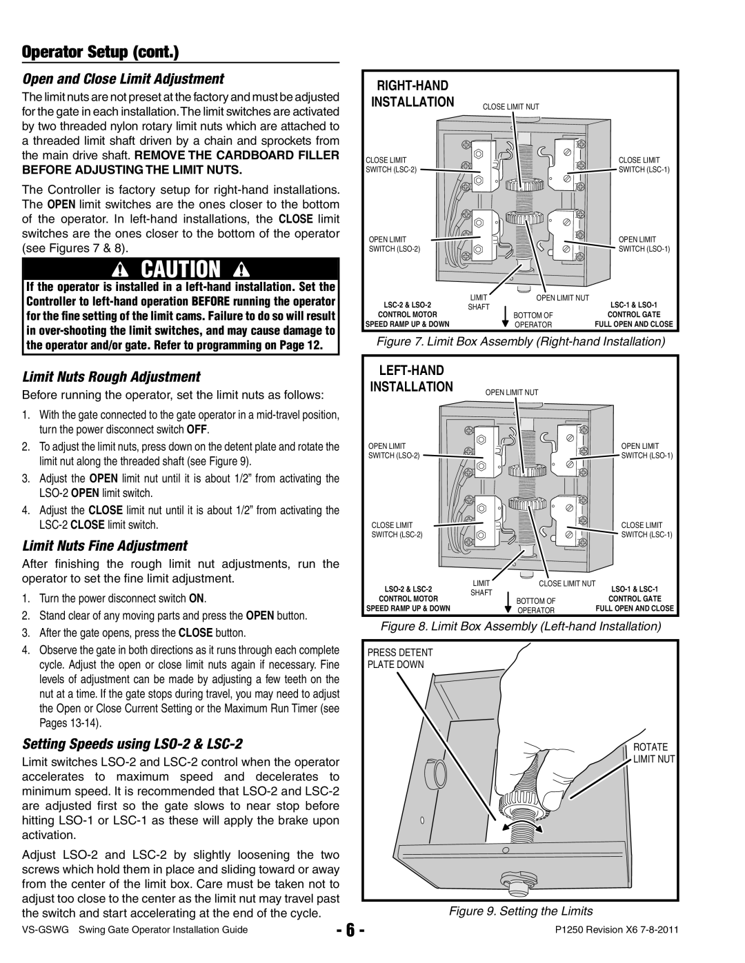
RIGHT-HAND
INSTALLATION | CLOSE LIMIT NUT |
CLOSE LIMIT | CLOSE LIMIT |
SWITCH | SWITCH |
OPEN LIMIT |
|
| OPEN LIMIT |
SWITCH |
|
| SWITCH |
LIMIT | OPEN LIMIT NUT | ||
SHAFT |
| ||
CONTROL MOTOR |
| BOTTOM OF | CONTROL GATE |
SPEED RAMP UP & DOWN |
| OPERATOR | FULL OPEN AND CLOSE |
Figure 7. Limit Box Assembly (Right-hand Installation)
Limit Nuts Rough Adjustment
Before running the operator, set the limit nuts as follows:
1.With the gate connected to the gate operator in a
2.To adjust the limit nuts, press down on the detent plate and rotate the limit nut along the threaded shaft (see Figure 9).
3.Adjust the OPEN limit nut until it is about 1/2” from activating the
4.Adjust the CLOSE limit nut until it is about 1/2” from activating the
Limit Nuts Fine Adjustment
After fi nishing the rough limit nut adjustments, run the operator to set the fine limit adjustment.
1.Turn the power disconnect switch ON.
2.Stand clear of any moving parts and press the OPEN button.
3.After the gate opens, press the CLOSE button.
4.Observe the gate in both directions as it runs through each complete cycle. Adjust the open or close limit nuts again if necessary. Fine levels of adjustment can be made by adjusting a few teeth on the nut at a time. If the gate stops during travel, you may need to adjust the Open or Close Current Setting or the Maximum Run Timer (see Pages
Setting Speeds using LSO-2 & LSC-2
Limit switches
Adjust
|
|
INSTALLATION | OPEN LIMIT NUT |
| |
OPEN LIMIT | OPEN LIMIT |
SWITCH | SWITCH |
CLOSE LIMIT |
|
| CLOSE LIMIT | |
SWITCH |
|
| SWITCH | |
LIMIT | CLOSE LIMIT NUT | |||
SHAFT |
| |||
CONTROL MOTOR | BOTTOM OF | CONTROL GATE | ||
| ||||
SPEED RAMP UP & DOWN |
| OPERATOR | FULL OPEN AND CLOSE |
Figure 8. Limit Box Assembly (Left-hand Installation)
PRESS DETENT |
PLATE DOWN |
ROTATE |
LIMIT NUT |
Figure 9. Setting the Limits
- 6 - | P1250 Revision X6 | |
|