Dual Gate Installations
Two operators can be used in dual gate installations. The operators communicate with each other through the
When one operator activates, the COMM LINK connection signals the other operator to activate. Each operator functions independently, controlling its gate and monitoring its inputs and accessories.
A
✓NOTE: The shield wire should be connected COMM LINK terminal “C” in both operators.
Three of the programming functions available are only used for dual gate installations:
•Dual Gate Enable
Dual Gate Enable must be set for all dual gate installations.
•Stagger Mode
The Stagger Mode function determines if the operator has a delayed open or a delayed close. In dual swing gate installations, typically one operator is programmed for delayed open, and the other operator is programmed for delayed close.
•Stagger Delay Time
The Stagger Time sets the length of the delay for the Stagger Mode.
See Pages 12 & 14 for details on these three dual gate programming functions.
Set the following parameters in each gate operator individually in a single gate mode before connecting the network cable and operating in dual gate mode.
1.Open and Close Limit settings
2.Open and Closed direction inherent entrapment protection (OC & CC)
After these parameters have been set, and each operator has been tested independently and is functioning correctly in single gate mode, then set BOTH operators to dual gate (dg) in the Paired Mode setup step under Basic Programming steps.
DUAL GATE |
|
|
|
| OPERATOR #1 | ||||
COMM LINK |
|
|
|
| |||||
SHIELD |
|
|
|
|
|
|
| ||
WIRING |
|
|
|
|
|
|
| ||
|
|
|
|
|
|
| |||
|
|
|
|
|
|
|
|
|
|
|
|
|
|
|
|
|
|
|
|
|
|
|
|
|
|
|
|
|
|
|
|
|
|
|
|
|
|
|
|
|
|
|
|
|
|
|
|
|
|
|
|
|
|
|
|
|
|
|
|
|
|
|
|
|
|
|
|
|
|
|
|
|
|
|
|
|
|
|
|
|
|
|
|
|
|
|
|
|
|
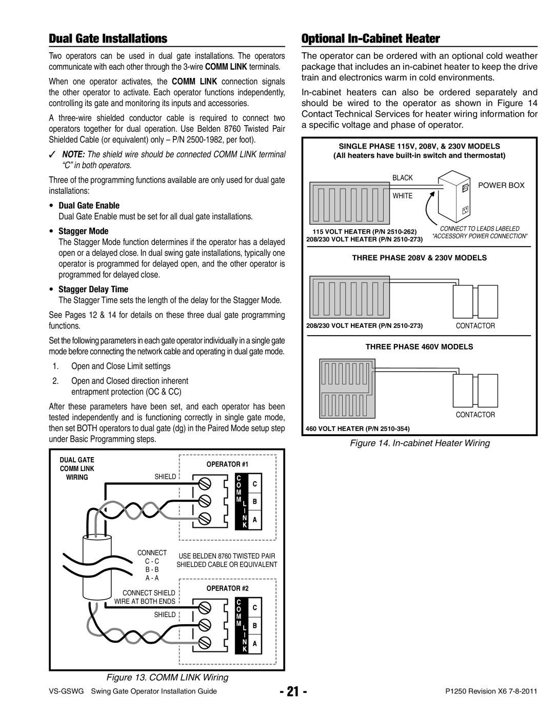
Optional In-Cabinet Heater
The operator can be ordered with an optional cold weather package that includes an
SINGLE PHASE 115V, 208V, & 230V MODELS (All heaters have
BLACK
| POWER BOX |
WHITE |
|
115 VOLT HEATER (P/N | CONNECT TO LEADS LABELED |
|
208/230 VOLT HEATER (P/N | "ACCESSORY POWER CONNECTION" | |
| ||
|
|
|
THREE PHASE 208V & 230V MODELS
208/230 VOLT HEATER (P/N | CONTACTOR | |
|
|
|
THREE PHASE 460V MODELS
CONTACTOR
460 VOLT HEATER (P/N
Figure 14. In-cabinet Heater Wiring
CONNECT
C - C
B - B
A - A
USE BELDEN 8760 TWISTED PAIR SHIELDED CABLE OR EQUIVALENT
CONNECT SHIELD WIRE AT BOTH ENDS
OPERATOR #2
SHIELD
Figure 13. COMM LINK Wiring
- 21 - | P1250 Revision X6 | |
|