5Cascade Screen

PC Program Instructions

5Cascade Screen

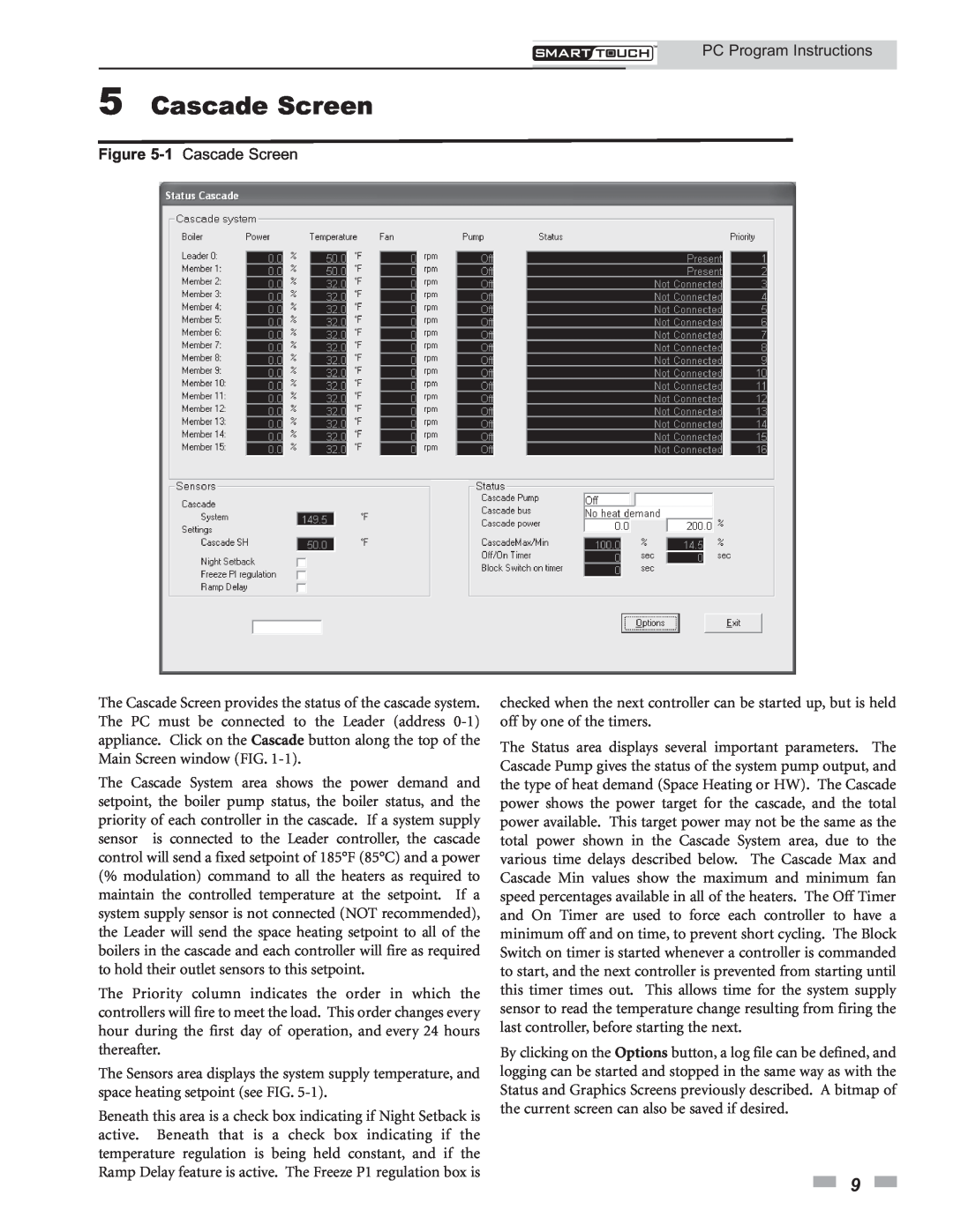
Figure 5-1Cascade Screen

The Cascade Screen provides the status of the cascade system. The PC must be connected to the Leader (address 0-1) appliance. Click on the Cascade button along the top of the Main Screen window (FIG. 1-1).

The Cascade System area shows the power demand and setpoint, the boiler pump status, the boiler status, and the priority of each controller in the cascade. If a system supply sensor is connected to the Leader controller, the cascade control will send a fixed setpoint of 185°F (85°C) and a power (% modulation) command to all the heaters as required to maintain the controlled temperature at the setpoint. If a system supply sensor is not connected (NOT recommended), the Leader will send the space heating setpoint to all of the boilers in the cascade and each controller will fire as required to hold their outlet sensors to this setpoint.

The Priority column indicates the order in which the controllers will fire to meet the load. This order changes every hour during the first day of operation, and every 24 hours thereafter.

The Sensors area displays the system supply temperature, and space heating setpoint (see FIG. 5-1).

Beneath this area is a check box indicating if Night Setback is active. Beneath that is a check box indicating if the temperature regulation is being held constant, and if the Ramp Delay feature is active. The Freeze P1 regulation box is

checked when the next controller can be started up, but is held off by one of the timers.

The Status area displays several important parameters. The Cascade Pump gives the status of the system pump output, and the type of heat demand (Space Heating or HW). The Cascade power shows the power target for the cascade, and the total power available. This target power may not be the same as the total power shown in the Cascade System area, due to the various time delays described below. The Cascade Max and Cascade Min values show the maximum and minimum fan speed percentages available in all of the heaters. The Off Timer and On Timer are used to force each controller to have a minimum off and on time, to prevent short cycling. The Block Switch on timer is started whenever a controller is commanded to start, and the next controller is prevented from starting until this timer times out. This allows time for the system supply sensor to read the temperature change resulting from firing the last controller, before starting the next.

By clicking on the Options button, a log file can be defined, and logging can be started and stopped in the same way as with the Status and Graphics Screens previously described. A bitmap of the current screen can also be saved if desired.

9

Page 9
Image 9
Lochinvar 1.3, 1.5 operation manual 5Cascade Screen, 1 Cascade Screen, PC Program Instructions

1.5, 1.3, 1 specifications

Lochinvar 1 is a remarkable achievement in the realm of modern technology and engineering. As a powerful and efficient water heater, it has been designed to cater to a wide range of residential and commercial needs. One of the standout features of Lochinvar 1 is its advanced heating technology, which incorporates a high-efficiency condensing design. This technology allows the unit to achieve impressive energy savings by maximizing heat transfer while minimizing energy consumption.

The Lochinvar 1 utilizes a stainless steel heat exchanger that enhances durability and corrosion resistance. This not only extends the lifespan of the unit but also ensures consistent performance over time. Coupled with a user-friendly control system, users can easily adjust settings and monitor performance, enhancing overall convenience and usability.

Another key characteristic of the Lochinvar 1 is its compact design, making it suitable for a variety of installation environments. Whether in a residential basement or a commercial utility room, the unit’s space-saving configuration allows for efficient use of available area without compromising on capability.

Safety features are integral to the Lochinvar 1, providing peace of mind for users. The unit is equipped with advanced monitoring systems that can detect irregularities and automatically shut down the system if necessary. This not only protects the equipment but also enhances the safety of the environment in which it operates.

In terms of performance, Lochinvar 1 boasts a high recovery rate, ensuring hot water is available on demand. This is particularly beneficial for settings with high water usage, allowing simultaneous operations without lag.

Moreover, the unit supports various venting options, offering flexibility during installation. Whether using traditional vertical venting or innovations like direct venting, Lochinvar 1 accommodates different building designs and local codes, making it highly versatile.

In conclusion, Lochinvar 1 epitomizes the melding of efficiency, reliability, and user-friendly technology. With its high-performance features, robust safety systems, and adaptable installation options, it stands out as a forefront player in the water heating industry, meeting the diverse needs of today's consumers and businesses alike.