Installation & Operation Manual

13 Diagrams

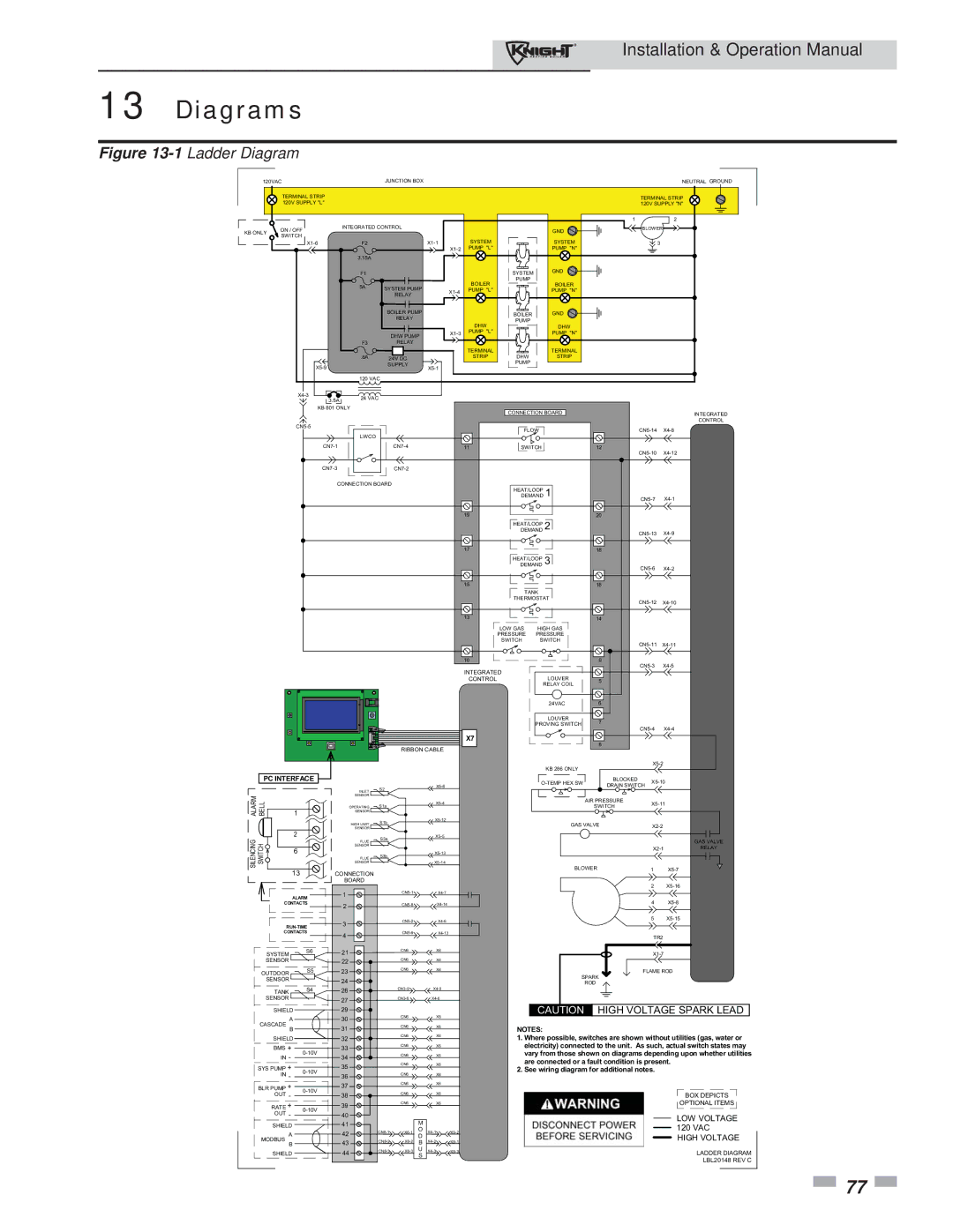
Figure 13-1Ladder Diagram

120VAC


JUNCTION BOX


NEUTRAL GROUND


TERMINAL STRIP


TERMINAL STRIP


120V SUPPLY "L"


120V SUPPLY "N"


1

2

KB ONLY

ON / OFF

INTEGRATED CONTROL


GND

BLOWER


SWITCH


SYSTEM


SYSTEM


X1-6

F2


X1-1


3


X1-2

PUMP "L"


PUMP "N"


3.15A


F1


SYSTEM

GND


BOILER

PUMP

BOILER


5A

SYSTEM PUMP


X1-4

PUMP "L"


PUMP "N"


RELAY


BOILER PUMP


BOILER

GND


RELAY


PUMP


DHW

DHW


DHW PUMP

X1-3

PUMP "L"


PUMP "N"


F3

RELAY


TERMINAL


TERMINAL


.8A

24V DC


STRIP

DHW

STRIP


X5-9


SUPPLY

X5-1


PUMP


120 VAC


X4-3

24 VAC


3.5A


KB 801 ONLY


CONNECTION BOARD


INTEGRATED


CN5-5


CONTROL


FLOW


CN5-14

X4-8


LWCO


CN7-1


CN7-4


11

SWITCH


12


CN5-10

X4-12


CN7-3


CN7-2


CONNECTION BOARD


HEAT/LOOPDEMAND 1


CN5-7

X4-1


19

20


HEAT/LOOPDEMAND 2


CN5-13 X4-9


17

18


HEAT/LOOPDEMAND 3


CN5-6 X4-2


15

16


TANK


THERMOSTAT


CN5-12 X4-10


13

14


LOW GAS

HIGH GAS


PRESSURE PRESSURE


SWITCH

SWITCH


CN5-11 X4-11


10


9

CN5-3 X4-5


INTEGRATED


LOUVER


CONTROL

5


RELAY COIL


24VAC

6


LOUVER

7


PROVING SWITCH

CN5-4

X4-4


X7


8


RIBBON CABLE


KB 286 ONLY


X5-2


PC INTERFACE


O-TEMP HEX SW

BLOCKED


X5-10


X5-6


DRAIN SWITCH


S2


INLET


ALARM BELL

1

SENSOR


AIR PRESSURE


X5-4


X5-11


OPERATING

S1a


SWITCH


SENSOR


HIGH LIMIT

S1b


X5-12


GAS VALVE


X2-2


2

SENSOR


SILENCING SWITCH


S3a


X5-5


GAS VALVE


FLUE


6

SENSOR


X2-1

RELAY


X5-13


S3b


FLUE


SENSOR


X5-14


BLOWER


13

CONNECTION


1

X5-7


BOARD


2

X5-16


ALARM

1


CN5-1


X4-7


CONTACTS

2


CN5-8


X4-14


4

X5-8


3


CN5-2


X4-6


5

X5-15


RUN-TIME


CONTACTS

4


CN5-9


X4-13


TR2


SYSTEM

S6

21


CN6


X6


X1-7


SENSOR


22


CN6


X6


OUTDOOR

S5

23


CN6


X6


FLAME ROD


SPARK

SENSOR


24


S4


CN3-9


ROD


TANK

26


X4-9


SENSOR


27


CN3-6


X4-6


CAUTION

HIGH VOLTAGE SPARK LEAD

SHIELD


29


CN6


X6


A


30


CASCADE


31


CN6


X6

NOTES:


B


SHIELD


32


CN6


X6

1. Where possible, switches are shown without utilities (gas, water or


BMS +


33


CN6


X6


electricity) connected to the unit. As such, actual switch states may

0-10V


vary from those shown on diagrams depending upon whether utilities

IN -

34


CN6


X6


CN6


are connected or a fault condition is present.

SYS PUMP +


35


X6


0-10V


2. See wiring diagram for additional notes.


IN -


36


CN6


X6


BLR PUMP +


37


CN6


X6


0-10V


OUT -

38


CN6


X6


BOX DEPICTS


RATE +

0-10V

39


CN6


X6


OPTIONAL ITEMS


OUT -

40


LOW VOLTAGE


M


SHIELD


41


120 VAC


CN8-1


O

X4-1


A


42

X6-1

D

X9-2


HIGH VOLTAGE

MODBUS B


43

CN8-2

X6-2

B

X4-2

X9-1


SHIELD


44

CN8-3

X6-3 U

X4-3

X9-3


LADDER DIAGRAM


S


LBL20148 REV C


77

Page 77
Image 77
Lochinvar 81 - 286 operation manual Diagrams, PC Interface

81 - 286 specifications

Lochinvar 81 - 286 is a state-of-the-art boiler recognized for its efficiency and reliability in both residential and commercial applications. This high-performance heating solution is designed to meet the diverse needs of users while adhering to modern environmental standards.

One of the standout features of the Lochinvar 81 - 286 is its advanced condensing technology. This allows the unit to harness more heat from the combustion gases, significantly boosting its thermal efficiency. With an impressive efficiency rating of over 95%, users can expect lower energy bills and reduced carbon emissions, making this boiler an environmentally friendly choice.

The Lochinvar 81 - 286 incorporates a robust stainless steel heat exchanger that guarantees durability and longevity. This corrosion-resistant material not only prolongs the unit's life but also ensures consistent performance over time. Additionally, the heat exchanger’s design facilitates optimal heat transfer, further enhancing the boiler's efficiency.

In terms of control, the Lochinvar 81 - 286 features a user-friendly control interface that simplifies operation. The boiler is equipped with advanced modulation capabilities, allowing it to adjust its output based on real-time heating demands. This responsiveness reduces energy waste and optimizes comfort levels within the space it serves.

The boiler also supports a variety of installation configurations, providing flexibility for different building layouts. Its compact design allows for easy installation in restricted spaces, while versatile venting options facilitate integration into various systems.

Safety is a paramount consideration in the design of the Lochinvar 81 - 286. The unit comes with integrated safety features such as a built-in diagnostic system that alerts users to any potential issues before they escalate. This proactive technology helps in maintaining seamless operation and reducing downtime.

Finally, the Lochinvar 81 - 286 is compliant with the latest regulations and industry standards, ensuring that it meets the expectations of both consumers and environmental agencies. With its impressive combination of efficiency, durability, and advanced technology, the Lochinvar 81 - 286 stands out as a top choice for anyone seeking a high-performance heating solution. This boiler not only addresses the immediate needs of heating but also supports long-term sustainability initiatives, proving to be a wise investment for the future.