5 Vertical direct venting

Vent/air termination – vertical

Installation & Operation Manual

￿WARNING

￿WARNING

NOTICE

Follow instructions below when determining vent location to avoid possibility of severe personal injury, death or substantial property damage.

Do not connect any other appliance to the vent pipe or multiple boilers to a common vent pipe. Failure to comply could result in severe personal injury, death, or substantial property damage.

Installation must comply with local requirements and with the National Fuel Gas Code, ANSI Z223.1 for U.S. installations or CSA B149.1 for Canadian installations.

￿WARNING Rooftop vent and air inlet terminations must terminate in the same pressure

zone, unless vertical vent sidewall air is set up as shown in the General Venting - Vertical Vent, Sidewall Air Section.

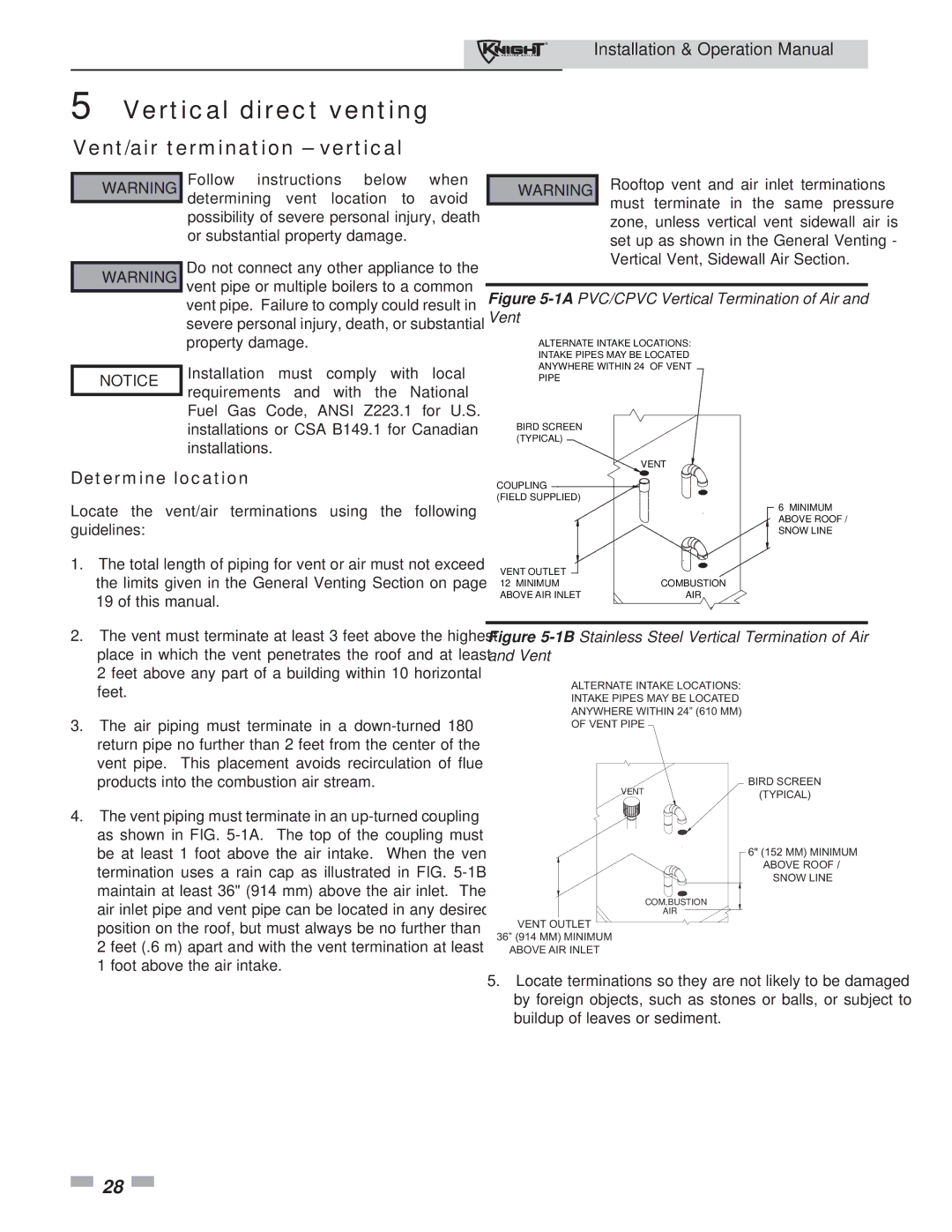
Figure 5-1APVC/CPVC Vertical Termination of Air and Vent

ALTERNATE INTAKE LOCATIONS:

INTAKE PIPES MAY BE LOCATED

ANYWHERE WITHIN 24” OF VENT

PIPE

BIRD SCREEN (TYPICAL)

Determine location

Locate the vent/air terminations using the following guidelines:

1.

The total length of piping for vent or air must not exceed


the limits given in the General Venting Section on page


19 of this manual.

2.

The vent must terminate at least 3 feet above the highest


place in which the vent penetrates the roof and at least


2 feet above any part of a building within 10 horizontal

VENT

COUPLING

(FIELD SUPPLIED)

6” MINIMUM ABOVE ROOF / SNOW LINE

VENT OUTLET

12” MINIMUM ABOVE AIR INLET

COMBUSTION

AIR

Figure 5-1BStainless Steel Vertical Termination of Air and Vent


feet.

3.

The air piping must terminate in a down-turned 180°


return pipe no further than 2 feet from the center of the


vent pipe. This placement avoids recirculation of flue


products into the combustion air stream.

4.

The vent piping must terminate in an up-turned coupling


as shown in FIG. 5-1A. The top of the coupling must

ALTERNATE INTAKE LOCATIONS: INTAKE PIPES MAY BE LOCATED ANYWHERE WITHIN 24” (610 MM)

OF VENT PIPE

VENT

BIRD SCREEN

(TYPICAL)

be at least 1 foot above the air intake. When the vent

termination uses a rain cap as illustrated in FIG. 5-1B

maintain at least 36" (914 mm) above the air inlet. The

air inlet pipe and vent pipe can be located in any desired

position on the roof, but must always be no further than

2 feet (.6 m) apart and with the vent termination at least

1 foot above the air intake.

6" (152 MM) MINIMUM

ABOVE ROOF /

SNOW LINE

COM,BUSTION

AIR

VENT OUTLET

36” (914 MM) MINIMUM

ABOVE AIR INLET

5.Locate terminations so they are not likely to be damaged by foreign objects, such as stones or balls, or subject to buildup of leaves or sediment.

28

Page 28
Image 28
Lochinvar 81 - 286 operation manual Vertical direct venting, Vent/air termination vertical

81 - 286 specifications

Lochinvar 81 - 286 is a state-of-the-art boiler recognized for its efficiency and reliability in both residential and commercial applications. This high-performance heating solution is designed to meet the diverse needs of users while adhering to modern environmental standards.

One of the standout features of the Lochinvar 81 - 286 is its advanced condensing technology. This allows the unit to harness more heat from the combustion gases, significantly boosting its thermal efficiency. With an impressive efficiency rating of over 95%, users can expect lower energy bills and reduced carbon emissions, making this boiler an environmentally friendly choice.

The Lochinvar 81 - 286 incorporates a robust stainless steel heat exchanger that guarantees durability and longevity. This corrosion-resistant material not only prolongs the unit's life but also ensures consistent performance over time. Additionally, the heat exchanger’s design facilitates optimal heat transfer, further enhancing the boiler's efficiency.

In terms of control, the Lochinvar 81 - 286 features a user-friendly control interface that simplifies operation. The boiler is equipped with advanced modulation capabilities, allowing it to adjust its output based on real-time heating demands. This responsiveness reduces energy waste and optimizes comfort levels within the space it serves.

The boiler also supports a variety of installation configurations, providing flexibility for different building layouts. Its compact design allows for easy installation in restricted spaces, while versatile venting options facilitate integration into various systems.

Safety is a paramount consideration in the design of the Lochinvar 81 - 286. The unit comes with integrated safety features such as a built-in diagnostic system that alerts users to any potential issues before they escalate. This proactive technology helps in maintaining seamless operation and reducing downtime.

Finally, the Lochinvar 81 - 286 is compliant with the latest regulations and industry standards, ensuring that it meets the expectations of both consumers and environmental agencies. With its impressive combination of efficiency, durability, and advanced technology, the Lochinvar 81 - 286 stands out as a top choice for anyone seeking a high-performance heating solution. This boiler not only addresses the immediate needs of heating but also supports long-term sustainability initiatives, proving to be a wise investment for the future.