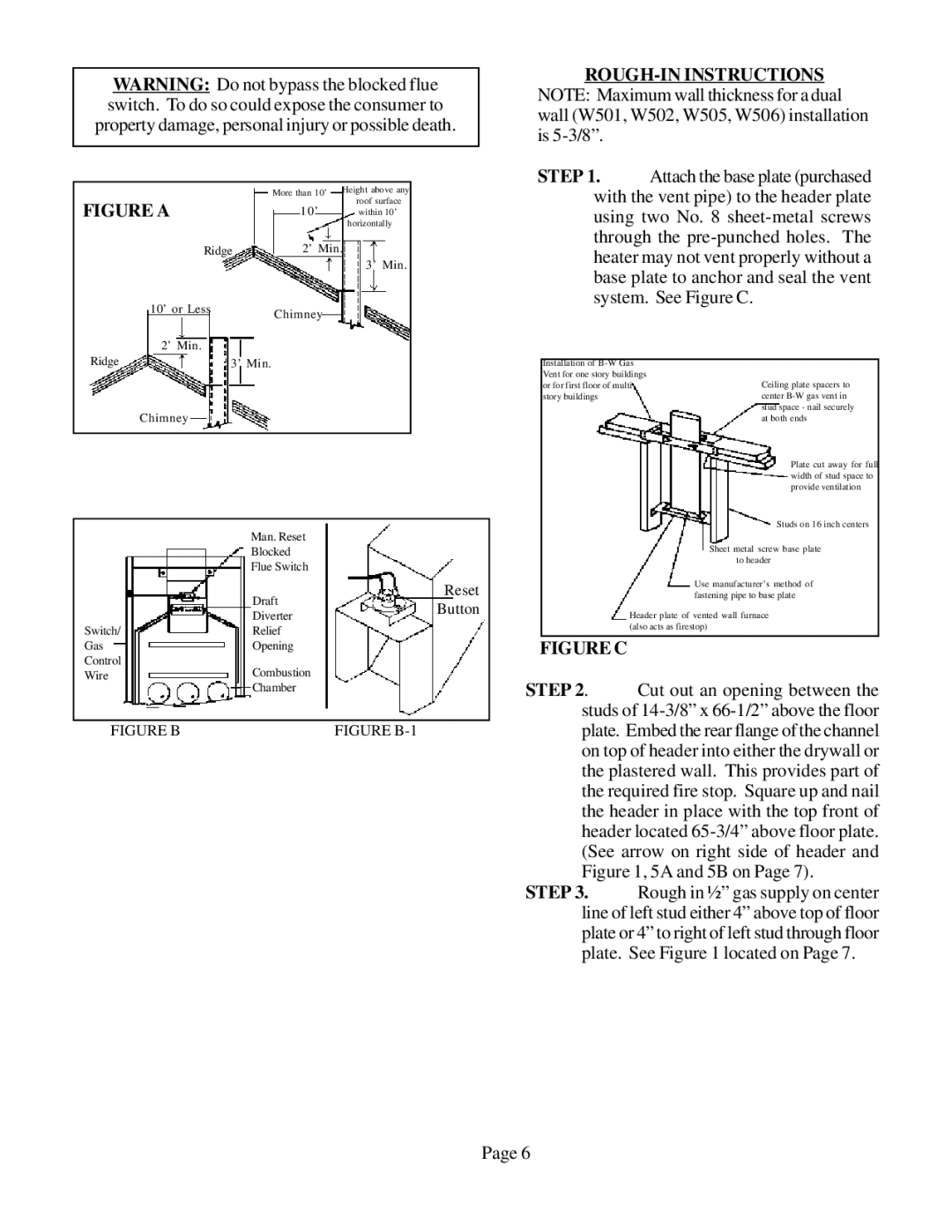
WARNING: Do not bypass the blocked flue switch. To do so could expose the consumer to property damage, personal injury or possible death.
| More than 10’ | Height above any | |
| roof surface | ||
FIGURE A | 1 0 ’ | ||
within 10’ | |||
|
| horizontally | |
Ridge | 2’ Min. | ||
|
| 3’ Min. | |
10’ or Less | Chimney |
| |
|
| ||
2’ Min. |
|
| |
STEP 1. Attach the base plate (purchased with the vent pipe) to the header plate using two No. 8
Ridge | 3’ Min. |
Chimney
Man. Reset |
| |
Blocked |
| |
Flue Switch |
| |
Draft | Reset | |
Button | ||
|
Installation of
Ceiling plate spacers to center
Plate cut away for full width of stud space to provide ventilation
Studs on 16 inch centers
Sheet metal screw base plate to header
Use manufacturer’s method of fastening pipe to base plate
| Diverter |
Switch/ | Relief |
Gas | Opening |
Control | Combustion |
Wire | |
| Chamber |
|
|
FIGURE B | FIGURE |
Header plate of vented wall furnace (also acts as firestop)
FIGURE C
STEP 2. Cut out an opening between the studs of
STEP 3. Rough in ½” gas supply on center line of left stud either 4” above top of floor plate or 4” to right of left stud through floor plate. See Figure 1 located on Page 7.
Page 6