TM
TM
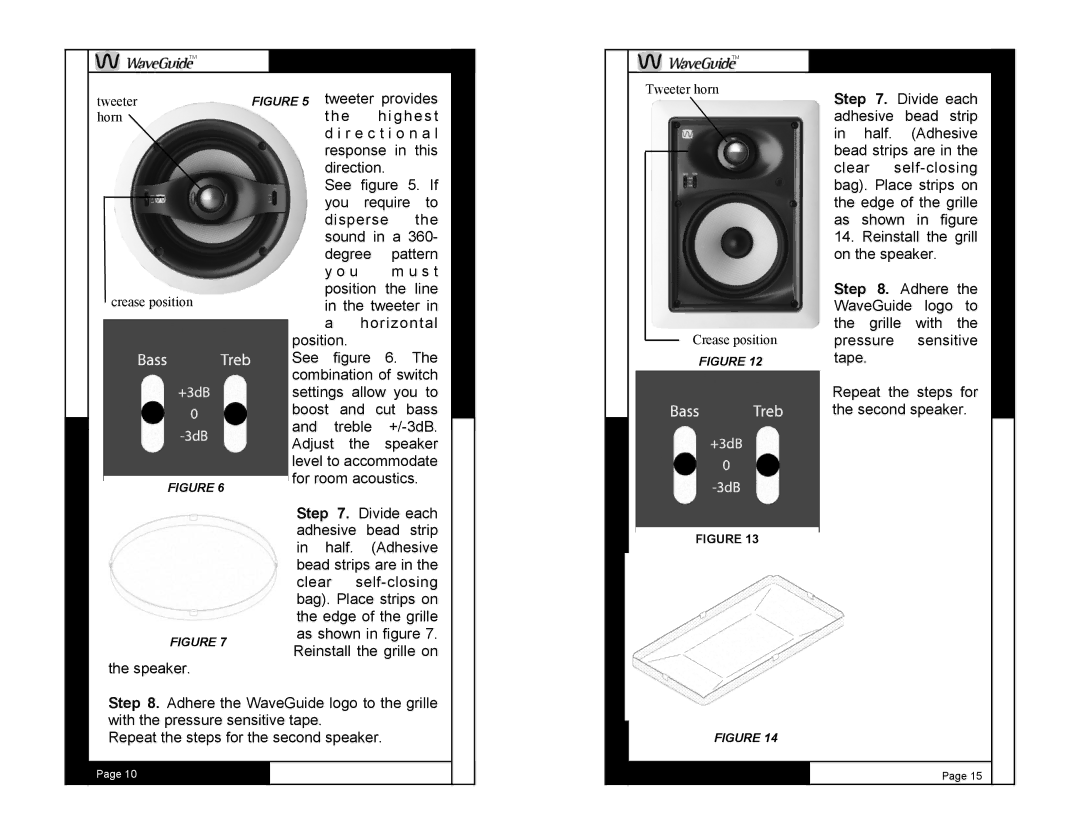
tweeter horn
crease position
FIGURE 6
tweeter provides t he highes t d i r e c t i o n a l response in this direction.
See figure 5. If you require to disperse the sound in a 360-
degree | pattern |
y o u | m u s t |
position | the line |
in the tweeter in
ahorizontal
position.
See figure 6. The combination of switch settings allow you to boost and cut bass and treble
Tweeter horn
Crease position
FIGURE 12
Step 7. Divide each adhesive bead strip in half. (Adhesive bead strips are in the clear
14.Reinstall the grill on the speaker.
Step 8. Adhere the WaveGuide logo to the grille with the pressure sensitive tape.
Repeat the steps for the second speaker.
FIGURE 7
the speaker.
Step 7. Divide each adhesive bead strip in half. (Adhesive bead strips are in the clear
FIGURE 13
Step 8. Adhere the WaveGuide logo to the grille with the pressure sensitive tape.
Repeat the steps for the second speaker.
Page 10
FIGURE 14
Page 15
