OUTPUT SECTION DESCRIPTION
|
|
|
|
|
| You’ve just learned about the | |||
|
|
|
| TM |
| input channels and how the sig- | |||
|
| 12V | |||||||
|
| 0.5A | nals get in and out. The signals | ||||||
|
|
| |||||||
| LAMP | ||||||||
|
|
|
|
| come in via MIC and LINE input | ||||
|
|
|
|
|
| ||||
| U |
| U | U |
| jacks, are manipulated by the | |||
1 |
| 1 |
| 1 | TO AUX | ||||
|
| SEND 1 | channels, and then sent to the | ||||||
OO | +10 | OO | +20 | OO | +15 EFFECTS TO | ||||
| U |
| U | U | MONITORS | output section. In the output | |||
|
|
|
|
| TO AUX | ||||
2 |
| 2 |
| 2 | section, things get a bit more | ||||
|
| SEND 2 | |||||||
OO | +10 | OO | +20 | OO | +15 | ||||
complicated, so put on your | |||||||||
AUX |
|
|
|
| |||||
SENDS |
| U | ASSIGN OPTIONS | thinking caps. |
|
| |||
1 |
| 3 |
|
|
|
|
| ||
|
|
|
|
|
|
| |||
SOLO |
| +20 | MAIN MIX | MAIN | |||||
|
| OO | TO SUBS | ||||||
2 |
|
| U |
|
| ||||
|
|
|
|
| |||||
|
|
|
|
|
|
|
| ||
SOLO | 4 |
|
|
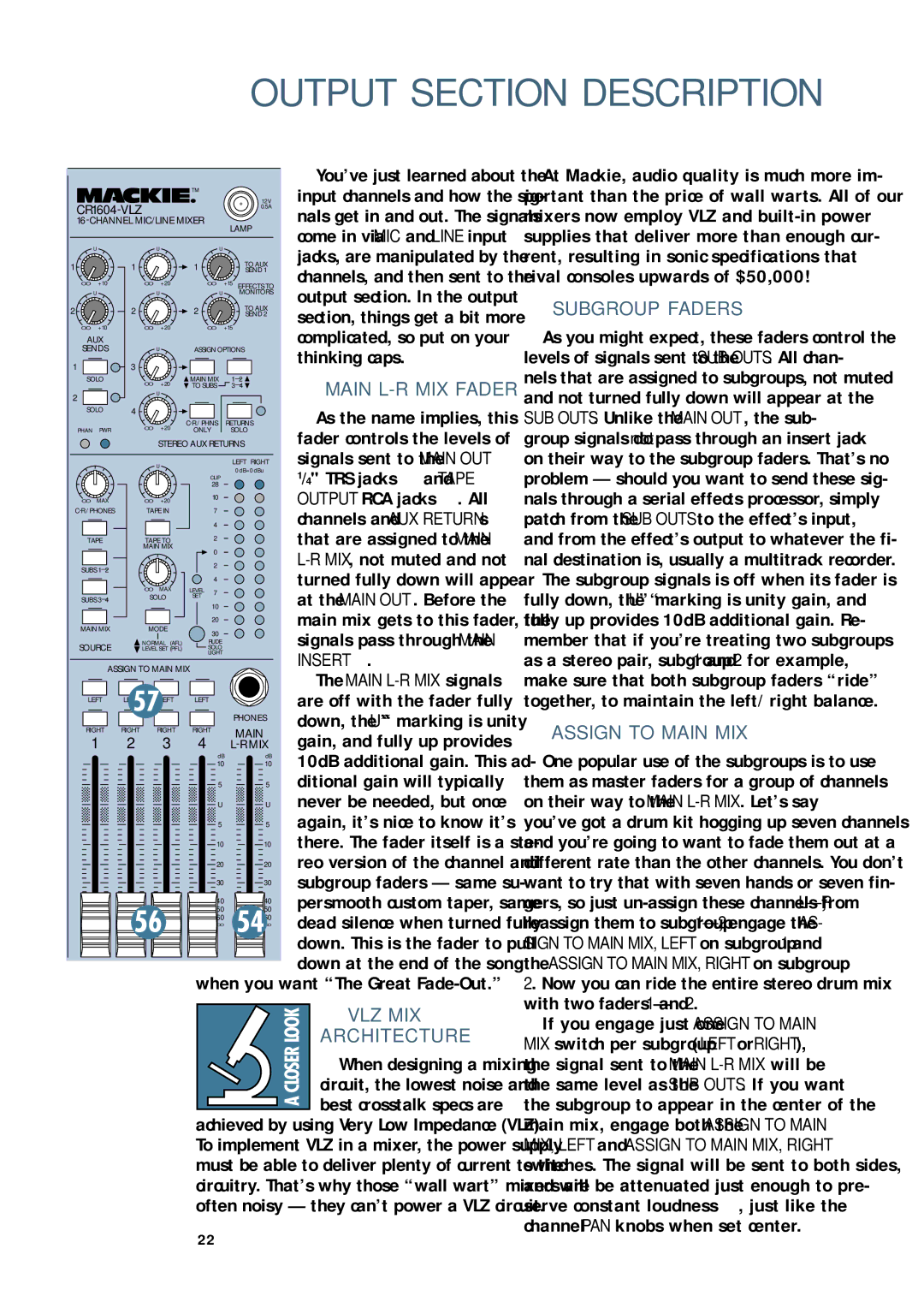
| As the name implies, this | ||||
|
| OO | +20 | RETURNS | |||||
PHAN | PWR | ONLY | SOLO | fader controls the levels of | |||||
|
|
| STEREO AUX RETURNS | ||||||
|
|
| U |
| LEFT RIGHT | signals sent to the MAIN OUT | |||
|
|
|
| CLIP | 0 dB=0 dBu | 1 | and TAPE | ||
|
|
|
| 28 |
| /4" TRS jacks | |||
OO | MAX | OO | +20 | 10 |
| OUTPUT RCA jacks | . All | ||
|
| ||||||||
TAPE IN | 7 |
| |||||||
| channels and AUX RETURNs | ||||||||
|
|
|
| 4 |
| ||||
TAPE | TAPE TO | 2 |
| that are assigned to the MAIN | |||||
|
| MAIN MIX | 0 |
| |||||
|
|
|
|
| |||||
SUBS |
|
| 2 |
| |||||
|
|
|
| turned fully down will appear | |||||
|
|
|
| 4 |
| ||||
|
| OO | MAX | LEVEL 7 |
| ||||
|
|
| at the MAIN OUT. Before the | ||||||
SUBS | SOLO | SET |
| ||||||
10 |
| ||||||||
|
|
|
|
| |||||
|
|
|
| 20 |
| main mix gets to this fader, the | |||
MAIN MIX | MODE |
|
| ||||||
30 |
| signals pass through the MAIN | |||||||
|
|
|
|
| |||||
SOURCE | NORMAL (AFL) | RUDE |
| ||||||
LEVEL SET (PFL) | SOLO |
| |||||||
|
|
|
| LIGHT |
| INSERT . |
|
| |
| ASSIGN TO MAIN MIX |
|
|
| |||||
|
| The MAIN | |||||||
|
|
|
|
|
| ||||
LEFT | LEFT | LEFT | LEFT |
| are off with the fader fully | ||||
|
|
|
|
|
| ||||
|
|
|
|
| PHONES | down, the “U” marking is unity | |||
RIGHT | RIGHT | RIGHT | RIGHT | MAIN | |||||
gain, and fully up provides | |||||||||
1 | 2 | 3 | 4 | ||||||
|
|
|
| dB | dB | 10dB additional gain. This ad- | |||
|
|
|
| 10 | 10 | ||||
|
|
|
| 5 | 5 | ditional gain will typically | |||
|
|
|
| U | U | never be needed, but once | |||
|
|
|
| 5 | 5 | again, it’s nice to know it’s | |||
|
|
|
| 10 | 10 | there. The fader itself is a ste- | |||
|
|
|
| 20 | 20 | reo version of the channel and | |||
|
|
|
| 30 | 30 | subgroup faders — same su- | |||
|
|
|
|
|
| ||||
|
|
|
| 40 | 40 | persmooth custom taper, same | |||
|
|
|
| 50 | 50 | ||||
|
|
|
| 60 | 60 | dead silence when turned fully | |||
|
|
|
| OO | OO | ||||
|
|
|
|
|
| ||||
|
|
|
|
|
| down. This is the fader to pull | |||
|
|
|
|
|
| down at the end of the song | |||
|
|
|
| when you want “The Great |
| ||||
VLZ MIX
ARCHITECTURE
When designing a mixing
circuit, the lowest noise and best crosstalk specs are
achieved by using Very Low Impedance (VLZ). To implement VLZ in a mixer, the power supply must be able to deliver plenty of current to the circuitry. That’s why those “wall wart” mixers are often noisy — they can’t power a VLZ circuit.
At Mackie, audio quality is much more im- portant than the price of wall warts. All of our mixers now employ VLZ and
SUBGROUP FADERS
As you might expect, these faders control the levels of signals sent to the SUB OUTS. All chan- nels that are assigned to subgroups, not muted and not turned fully down will appear at the SUB OUTS. Unlike the MAIN OUT, the sub- group signals do not pass through an insert jack on their way to the subgroup faders. That’s no problem — should you want to send these sig- nals through a serial effects processor, simply patch from the SUB OUTS to the effect’s input, and from the effect’s output to whatever the fi- nal destination is, usually a multitrack recorder.
The subgroup signals is off when its fader is fully down, the “U” marking is unity gain, and fully up provides 10dB additional gain. Re- member that if you’re treating two subgroups as a stereo pair, subgroup 1 and 2 for example, make sure that both subgroup faders “ride” together, to maintain the left/right balance.
ASSIGN TO MAIN MIX
One popular use of the subgroups is to use them as master faders for a group of channels on their way to the MAIN
If you engage just one ASSIGN TO MAIN MIX switch per subgroup (LEFT or RIGHT), the signal sent to the MAIN
22