Do’s and Don’ts of Fixed Installations
If you install sound systems into fixed installa- tions, there are a number of things that you can do to make your life easier and that increase the likelihood of the sound system operating in a predictable manner. Even if you don’t do fixed installations, these are good practices for any sound system, installed.
1.Do use
2.Don’t connect the XLR connector shell to pin 1 of the XLR connector (unless necessary for RFI shielding). Doing so is an invitation for a ground loop to come visiting.
3.Do ensure that your speaker lines and AC power lines are physically separated from your microphone lines.
4.If you use floor pockets, use separate pockets for inputs and speakers, or put the connectors on opposite sides of the box so that they may be shielded separately.
5.If your speaker lines run in the open, they should be twisted pairs, at least 6 twists per foot. Otherwise, run the speaker lines in their own conduit. (Of course, conduit is not too practical for portable systems,
6.Minimize the distance between the power amplifiers and the speakers.
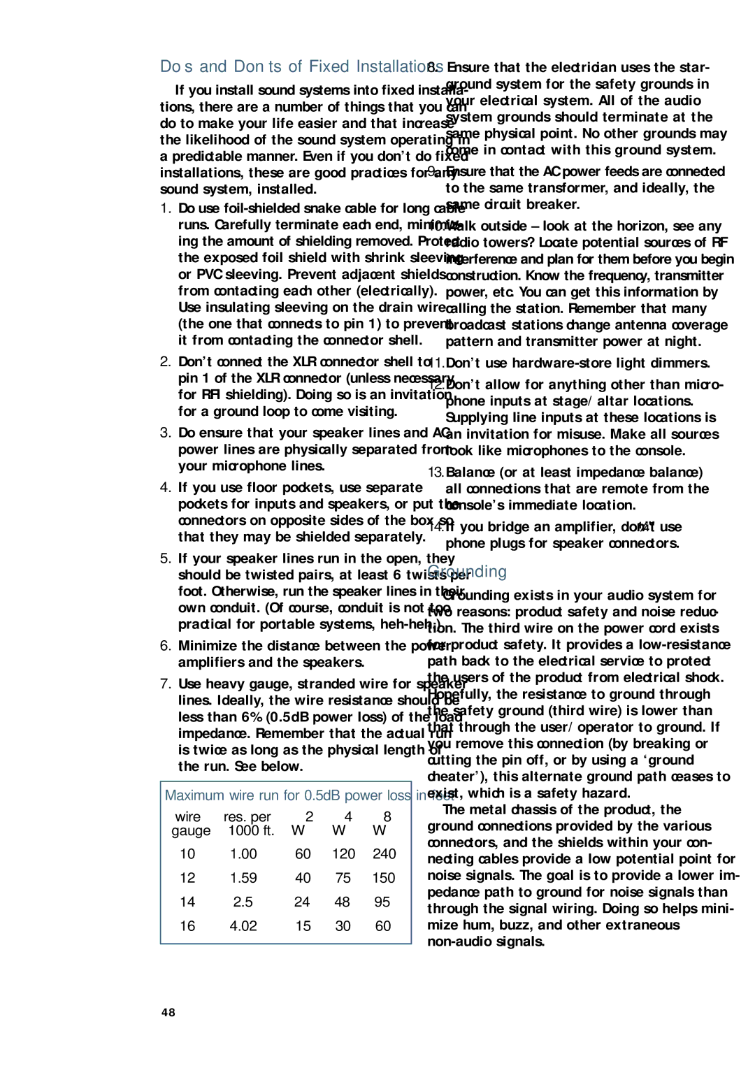
7.Use heavy gauge, stranded wire for speaker lines. Ideally, the wire resistance should be less than 6% (0.5dB power loss) of the load impedance. Remember that the actual run is twice as long as the physical length of the run. See below.
Maximum wire run for 0.5dB power loss in feet
wire | res. per | 2 | 4 | 8 |
gauge | 1000 ft. | Ω | Ω | Ω |
10 | 1.00 | 60 | 120 | 240 |
12 | 1.59 | 40 | 75 | 150 |
14 | 2.5 | 24 | 48 | 95 |
16 | 4.02 | 15 | 30 | 60 |
8. Ensure that the electrician uses the star- ground system for the safety grounds in your electrical system. All of the audio system grounds should terminate at the same physical point. No other grounds may come in contact with this ground system.
9.Ensure that the AC power feeds are connected to the same transformer, and ideally, the same circuit breaker.
10.Walk outside – look at the horizon, see any radio towers? Locate potential sources of RF interference and plan for them before you begin construction. Know the frequency, transmitter power, etc. You can get this information by calling the station. Remember that many broadcast stations change antenna coverage pattern and transmitter power at night.
11.Don’t use hardware-store light dimmers.
12.Don’t allow for anything other than micro- phone inputs at stage/altar locations. Supplying line inputs at these locations is an invitation for misuse. Make all sources look like microphones to the console.
13.Balance (or at least impedance balance) all connections that are remote from the console’s immediate location.
14.If you bridge an amplifier, don’t use 1⁄4" phone plugs for speaker connectors.
Grounding
Grounding exists in your audio system for two reasons: product safety and noise reduc- tion. The third wire on the power cord exists for product safety. It provides a
The metal chassis of the product, the ground connections provided by the various connectors, and the shields within your con- necting cables provide a low potential point for noise signals. The goal is to provide a lower im- pedance path to ground for noise signals than through the signal wiring. Doing so helps mini- mize hum, buzz, and other extraneous
48