P 5/ 8
 Repair
[3]-3. Spur Gear 29, Spiral Bevel Gear 9
ASSEMBLING
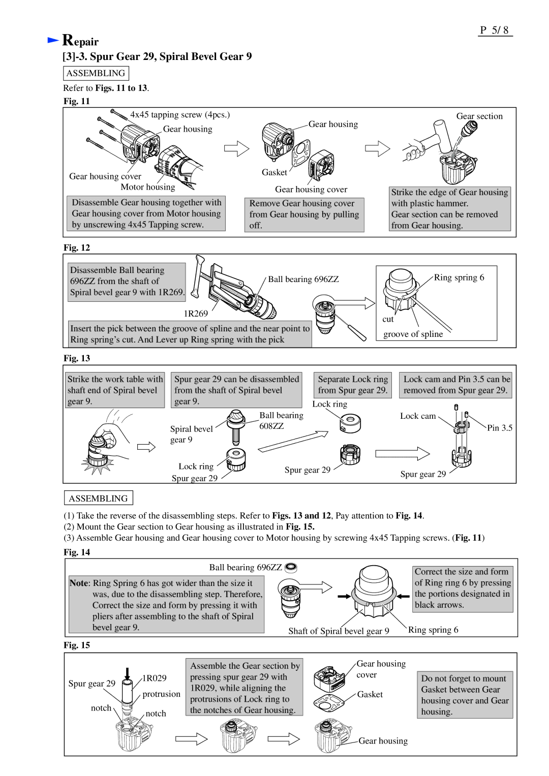
Refer to Figs. 11 to 13.
Fig. 11
![]() 4x45 tapping screw (4pcs.)
4x45 tapping screw (4pcs.)
Gear housing
Gear housing cover ![]()
![]()
![]()
![]()
![]()
![]()
![]()
![]()
![]()
![]() Motor housing
Motor housing ![]()
![]()
![]()
![]()
Disassemble Gear housing together with Gear housing cover from Motor housing by unscrewing 4x45 Tapping screw.
Gear housing
Gasket ![]()
Gear housing cover
Remove Gear housing cover from Gear housing by pulling off.
Gear section
Strike the edge of Gear housing with plastic hammer.
Gear section can be removed from Gear housing.
Fig. 12
Disassemble Ball bearing | Ball bearing 696ZZ |
696ZZ from the shaft of | |
Spiral bevel gear 9 with 1R269. |
|
1R269
Insert the pick between the groove of spline and the near point to Ring spring’s cut. And Lever up Ring spring with the pick
![]() Ring spring 6
Ring spring 6
cut ![]() groove of spline
groove of spline
Fig. 13
Strike the work table with shaft end of Spiral bevel gear 9.
Spur gear 29 can be disassembled from the shaft of Spiral bevel gear 9.
Separate Lock ring from Spur gear 29.
Lock ring
Lock cam and Pin 3.5 can be removed from Spur gear 29.
| Ball bearing | Lock cam | |
Spiral bevel | 608ZZ | Pin 3.5 | |
gear 9 |
|
| |
Lock ring | Spur gear 29 | Spur gear 29 | |
Spur gear 29 | |||
| |||
|
|
ASSEMBLING
(1)Take the reverse of the disassembling steps. Refer to Figs. 13 and 12, Pay attention to Fig. 14.
(2)Mount the Gear section to Gear housing as illustrated in Fig. 15.
(3)Assemble Gear housing and Gear housing cover to Motor housing by screwing 4x45 Tapping screws. (Fig. 11)
Fig. 14
|
| Ball bearing 696ZZ |
| Correct the size and form |
|
|
|
| |
Note: Ring Spring 6 has got wider than the size it |
| of Ring ring 6 by pressing | ||
was, due to the disassembling step. Therefore, |
| the portions designated in | ||
Correct the size and form by pressing it with |
| black arrows. | ||
pliers after assembling to the shaft of Spiral |
|
| ||
bevel gear 9. |
| Shaft of Spiral bevel gear 9 | Ring spring 6 | |
Fig. 15 |
|
|
|
|
|
| Assemble the Gear section by | Gear housing |
|
Spur gear 29 | 1R029 | pressing spur gear 29 with | cover | Do not forget to mount |
| 1R029, while aligning the |
| Gasket between Gear | |
| protrusion | Gasket | ||
| protrusions of Lock ring to | housing cover and Gear | ||
notch |
|
| ||
notch | the notches of Gear housing. |
| housing. | |
|
| |||
|
|
| Gear housing |
|
