P 10/ 16
 Repair
[3]DISASSEMBLY/ASSEMBLY
[3]-6. Blade Case Complete
DISASSEMBLING
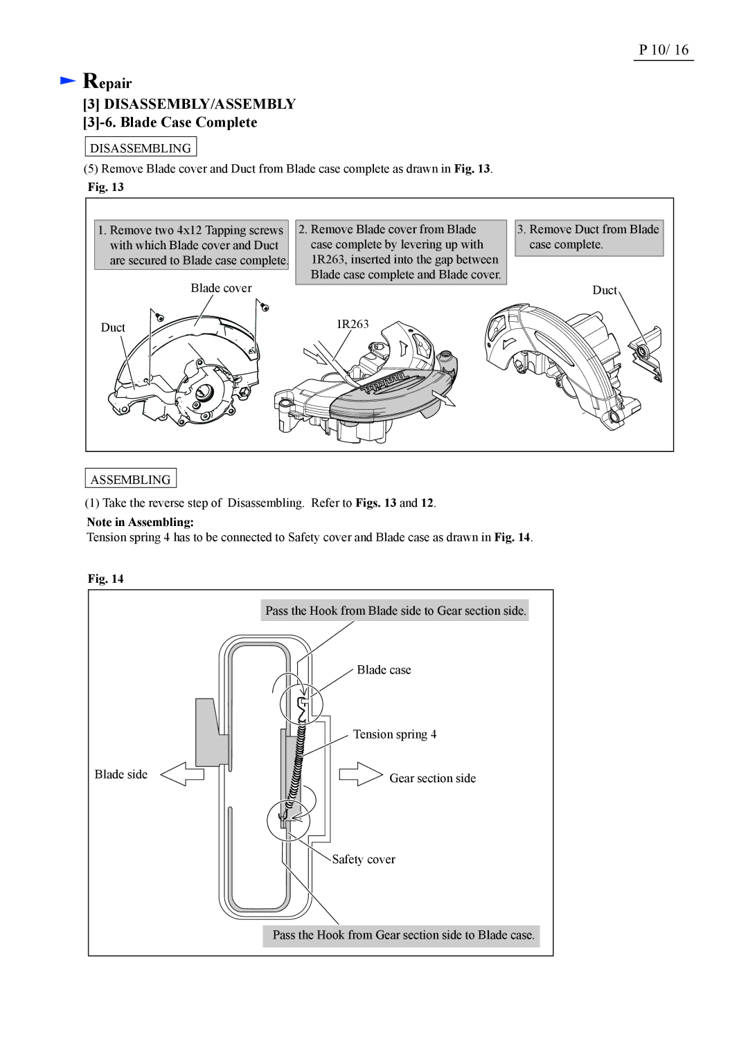
(5)Remove Blade cover and Duct from Blade case complete as drawn in Fig. 13.
Fig. 13
1. Remove two 4x12 Tapping screws | 2. Remove Blade cover from Blade | 3. Remove Duct from Blade |
with which Blade cover and Duct | case complete by levering up with | case complete. |
are secured to Blade case complete. | 1R263, inserted into the gap between |
|
Blade cover | Blade case complete and Blade cover. | Duct |
| ||
Duct | 1R263 |
|
ASSEMBLING
(1) Take the reverse step of Disassembling. Refer to Figs. 13 and 12.
Note in Assembling:
Tension spring 4 has to be connected to Safety cover and Blade case as drawn in Fig. 14.
Fig. 14
Pass the Hook from Blade side to Gear section side.
Blade case
| Tension spring 4 |
Blade side | Gear section side |
![]() Safety cover
Safety cover
Pass the Hook from Gear section side to Blade case.