P 7/ 16
 Repair
[3]DISASSEMBLY/ASSEMBLY
[3]-4. Angular Guide
DISASSEMBLING
Angular guide is fixed to the machine at the following 3 positions.
1.at the hinge portion fixed with Shoulder pin
2.at Angular plate on Base with M6x20 Thumb screw, Flat washer 6 and Spring washer 6
3.at Blade case section with M5 pan head screw and
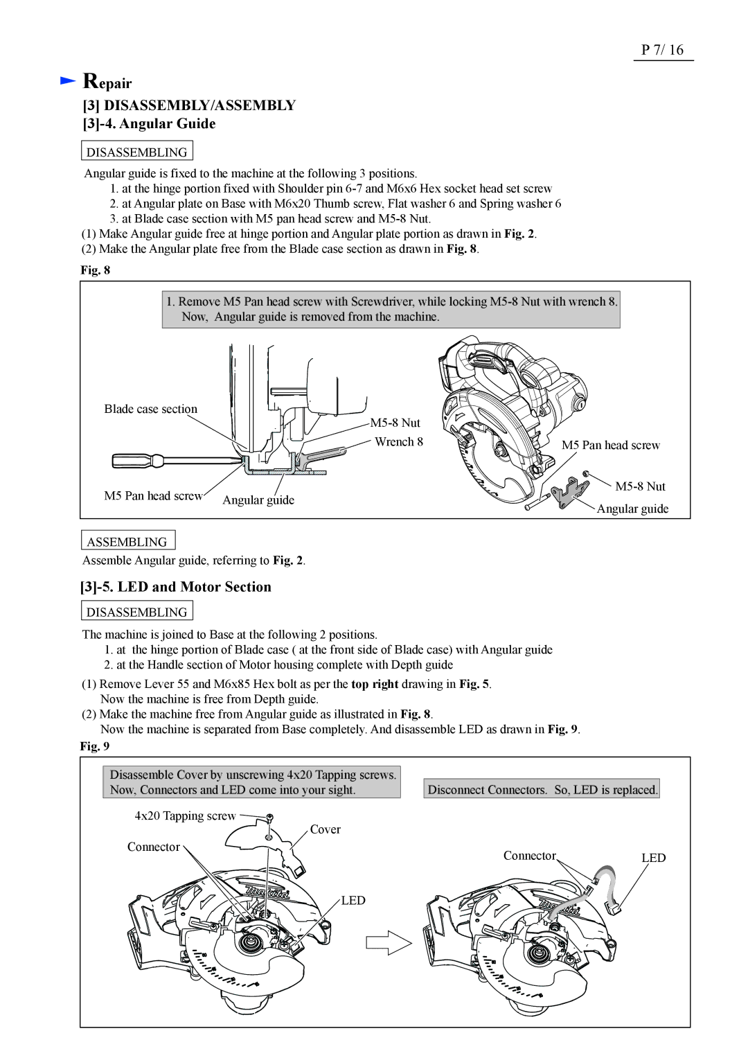
(1)Make Angular guide free at hinge portion and Angular plate portion as drawn in Fig. 2.
(2)Make the Angular plate free from the Blade case section as drawn in Fig. 8.
Fig. 8
1.Remove M5 Pan head screw with Screwdriver, while locking
Blade case section
![]() Wrench 8
Wrench 8
M5 Pan head screw | Angular guide |
|
M5 Pan head screw
![]()
![]()
![]()
![]()
![]()
![]() Angular guide
Angular guide
ASSEMBLING
Assemble Angular guide, referring to Fig. 2.
[3]-5. LED and Motor Section
DISASSEMBLING
The machine is joined to Base at the following 2 positions.
1.at the hinge portion of Blade case ( at the front side of Blade case) with Angular guide
2.at the Handle section of Motor housing complete with Depth guide
(1)Remove Lever 55 and M6x85 Hex bolt as per the top right drawing in Fig. 5. Now the machine is free from Depth guide.
(2)Make the machine free from Angular guide as illustrated in Fig. 8.
Now the machine is separated from Base completely. And disassemble LED as drawn in Fig. 9.
Fig. 9
Disassemble Cover by unscrewing 4x20 Tapping screws. Now, Connectors and LED come into your sight.
4x20 Tapping screw ![]()
![]()
Cover
Connector
Disconnect Connectors. So, LED is replaced.
ConnectorLED
LED
