P 4/ 16
 Repair
[3]DISASSEMBLY/ASSEMBLY
[3]-2. Lock Lever
ASSEMBLING
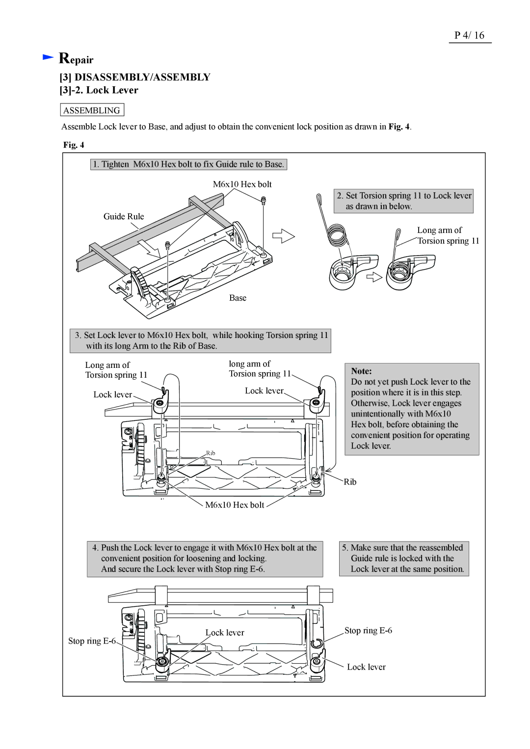
Assemble Lock lever to Base, and adjust to obtain the convenient lock position as drawn in Fig. 4.
Fig. 4
1.Tighten M6x10 Hex bolt to fix Guide rule to Base. M6x10 Hex bolt
Guide Rule
Base
2.Set Torsion spring 11 to Lock lever as drawn in below.
Long arm of
![]() Torsion spring 11
Torsion spring 11
3.Set Lock lever to M6x10 Hex bolt, while hooking Torsion spring 11 with its long Arm to the Rib of Base.
Long arm of | long arm of |
Torsion spring 11 | Torsion spring 11 |
Lock lever | Lock lever |
|
Rib
![]() M6x10 Hex bolt
M6x10 Hex bolt
Note:
Do not yet push Lock lever to the position where it is in this step. Otherwise, Lock lever engages unintentionally with M6x10 Hex bolt, before obtaining the convenient position for operating Lock lever.
![]()
![]() Rib
Rib
4.Push the Lock lever to engage it with M6x10 Hex bolt at the convenient position for loosening and locking.
And secure the Lock lever with Stop ring
5.Make sure that the reassembled Guide rule is locked with the Lock lever at the same position.
Lock lever | Stop ring |
Stop ring |
|
![]() Lock lever
Lock lever
