P 3/ 16
 Repair
[3]DISASSEMBLY/ASSEMBLY
[3]-1. Base
DISASSEMBLING
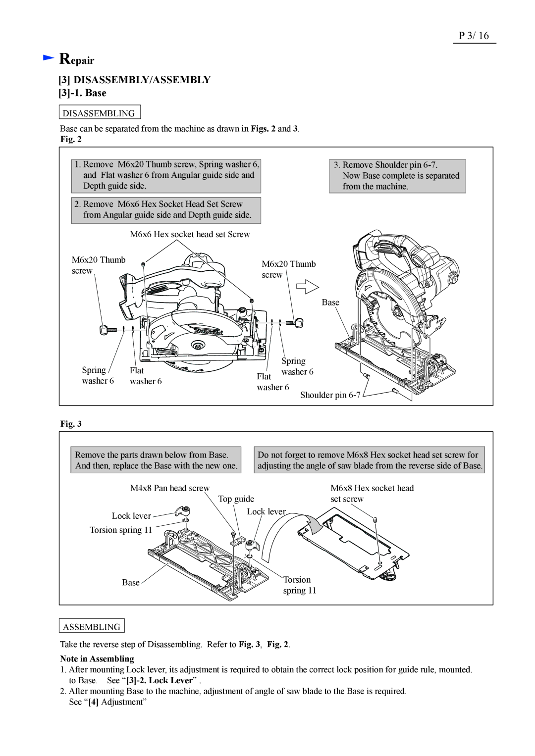
Base can be separated from the machine as drawn in Figs. 2 and 3.
Fig. 2
1.Remove M6x20 Thumb screw, Spring washer 6, and Flat washer 6 from Angular guide side and Depth guide side.
2.Remove M6x6 Hex Socket Head Set Screw from Angular guide side and Depth guide side.
3.Remove Shoulder pin
Now Base complete is separated from the machine.
| M6x6 Hex socket head set Screw | |
M6x20 Thumb | M6x20 Thumb | |
screw | ||
screw | ||
|
Base
Spring | Flat |
washer 6 | washer 6 |
| Spring | |
Flat | washer 6 | |
|
| |
washer 6 | Shoulder pin | |
|
| |
Fig. 3
Remove the parts drawn below from Base. And then, replace the Base with the new one.
Do not forget to remove M6x8 Hex socket head set screw for adjusting the angle of saw blade from the reverse side of Base.
M4x8 Pan head screw | Top guide | M6x8 Hex socket head |
| set screw | |
Lock lever | Lock lever | |
|
| |
Torsion spring 11 |
|
|
Base |
| Torsion |
|
| spring 11 |
ASSEMBLING
Take the reverse step of Disassembling. Refer to Fig. 3, Fig. 2.
Note in Assembling
1.After mounting Lock lever, its adjustment is required to obtain the correct lock position for guide rule, mounted. to Base. See
2.After mounting Base to the machine, adjustment of angle of saw blade to the Base is required. See “[4] Adjustment”