Repair |
|
| |
[3] DISASSEMBLY/ASSEMBLY | Fig. 38 |
| |
[3] |
|
| |
ASSEMBLING |
| Pin 2.5 | |
(7) Insert the remaining two Pins 2.5 firmly into Housing set L until they stop | (Ref. Figs. 34 and 35) | ||
| |||
as drawn in Fig. 38. |
| Pin 2.5 (2pcs.) | |
(8) Install Link plate to Housing L with Pin 3 through Link plate. (Fig. 39) |
| ||
(9) Insert the projection of Light switch arm into Compression spring 2 |
| ||
firmly. And then insert the axis of Light switch arm into hole of | Housing Fig. 39 |
| |
L and push Compression spring 2 to the emboss of Housing L. (Fig. 40) | Pin 3 | ||
(10) Set Torsion spring 4 in place. Install Safety trigger and Torsion spring 4 | |||
Link plate | |||
to Housing L with Pin 3 as drawn in Fig. 41. |
| ||
|
| ||
All the components are assembled as drawn in Fig. 42. |
|
| |
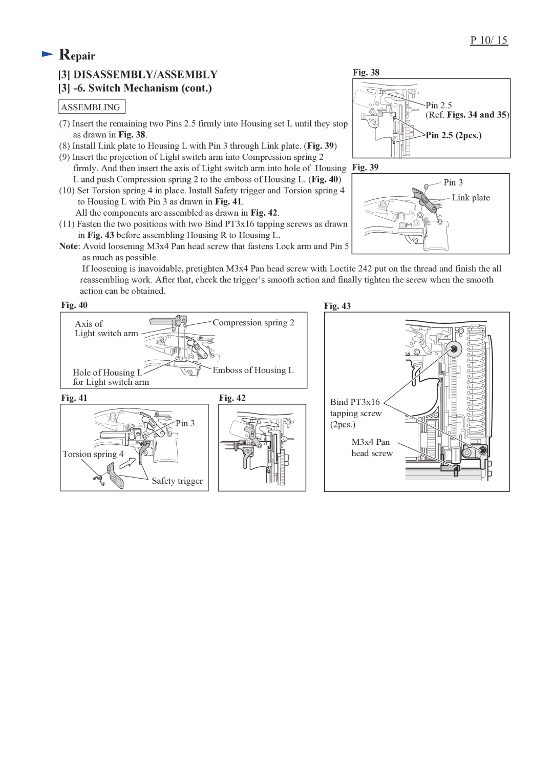
(11) Fasten the two positions with two Bind PT3x16 tapping screws as drawn |
| ||
in Fig. 43 before assembling Housing R to Housing L. |
|
| |
Note: Avoid loosening M3x4 Pan head screw that fastens Lock arm and Pin 5 |
| ||
as much as possible. |
|
| |
If loosening is inavoidable, pretighten M3x4 Pan head screw with Loctite 242 put on the thread and finish the all | |||
reassembling work. After that, check the trigger’s smooth action and finally tighten the screw when the smooth | |||
action can be obtained. |
|
| |
Fig. 40 | Fig. 43 |
| |
Axis of | Compression spring 2 |
Light switch arm |
|
Hole of Housing L ![]()
![]()
![]()
![]() Emboss of Housing L for Light switch arm
Emboss of Housing L for Light switch arm
Fig. 41 | Fig. 42 |
![]()
![]()
![]()
![]()
![]()
![]() Pin 3
Pin 3
Torsion spring 4
Safety trigger
Bind PT3x16 tapping screw (2pcs.)
M3x4 Pan head screw