 Repair
[3] DISASSEMBLY/ASSEMBLY
P 4/ 15
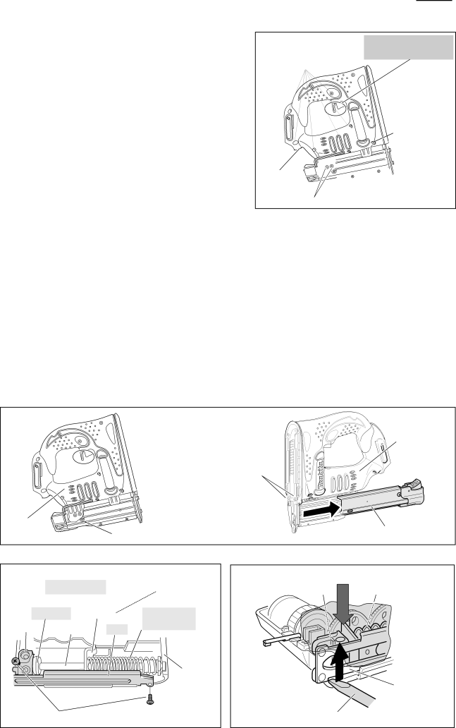
Fig. 9
[3] -2. Replacing Switch, LED circuit and Terminal
(1) | Do the steps (1), (2), (3) and (4) of the previous page. |
(2) | Insert Battery and pull the trigger to locate Hammer at |
| lowest position to release tension of Compression spring 17. |
| Remove Battery after this procedure is finished. |
| Go to the next step without changing spring position |
| in case Switch or DC motor is disorder. |
(3) | Separate housing R by removing Tapping screws and Pan head |
| screws drawn in Fig. 9 while holding trigger section |
| to prevent spring from jumping out. |
Bind PT3x16 Tapping screw for Housing L and R (8pcs.) ![]()
![]()
Hold trigger section so as not to spring out.
Housing L (The reverse ![]() of Housing R)
of Housing R)
M4x35 Pan
![]() head screw
head screw
(4) Switch, LED circuit and Terminal now can be removed. |
Housing R ![]()
![]()
M4x14 Pan head screw (2pcs.)
[3]-3. Replacing Motor
(1)Remove Front cover and Housing R as drawn in Fig. 2 and Fig. 9.
(2)Remove M4x6 Hex socket head bolt. Pull out Upper rail complete, and then separate Magazine ass'y from Housing L by removing two M4x10 Hex socket head bolts. (Fig. 10)
(3)Dismantle Housing R by removing 8 pcs. of Bind PT3x16 Tapping screws, 2 psc of M4x14 Pan head screw and a M4x35 PAn head screw. Now DC motor can be removed provided Compression spring 17 has no tension.
(4)When Motor or Switch is out of order, Hammer of Spring section often stops in the halfway position and Compression spring 17 remains compressed. It is impossible to remove DC motor from Housing L.
In this condition, remove 2pcs. of Bin PT3x16 Tapping screw (Fig.11), and insert slotted screwdriver into the gap between Housing L and Rail of Spring section, and then lever up Spring section with the slotted screwdriver
as drawn in Fig. 12.
Note • Cover Spring section with cloth in order not to pinch your finger.
•Hold Spring section by hand to prevent Compression spring 17 from jumping out.
(5)Remove Motor from Housing L.
Fig. 10
|
|
|
| Housing L |
|
| M4x10 Hex socket |
| |
|
| head bolt (2pcs.) |
| |
Housing R | M4x6 Hex socket head bolt |
| Upper rail complete | |
|
| |||
Fig. 11 |
|
| Fig. 12 |
|
|
| Hammer stops in | Cover Spring section with cloth and hold them by hand. | |
Spring section |
| the halfway position | Holder | Compression spring 17 |
|
|
| ||
Cushion Hammer | Compression |
|
| |
Holder Guide bolt | Rail | spring 17 |
|
|
|
|
| ||
|
| Housing L |
| Rail |
|
|
|
| |
Bind PT3x16 Tapping screw (2pcs.) | Slotted screwdriver | |||
