Wiring diagram
P 14/ 15
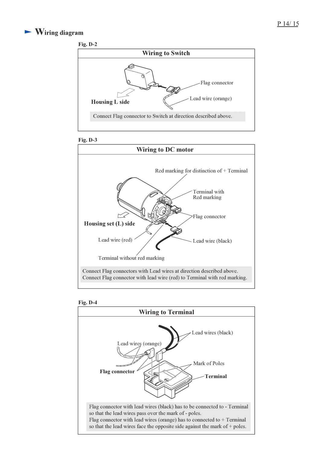
Fig. D-2
Wiring to Switch
| Flag connector |
Housing L side | Lead wire (orange) |
|
Connect Flag connector to Switch at direction described above.
Fig. D-3
Wiring to DC motor
| Red marking for distinction of + Terminal |
| Terminal with |
| Red marking |
Housing set (L) side | Flag connector |
| |
Lead wire (red) | Lead wire (black) |
Terminal without red marking
Connect Flag connectors with Lead wires at direction described above. Connect Flag connector with lead wire (red) to Terminal with red marking.
Fig. D-4
Wiring to Terminal
Lead wires (black)
Lead wires (orange)
Flag connector 
![]()
Mark of Poles
Terminal
Flag connector with lead wires (black) has to be connected to - Terminal so that the lead wires pass over the mark of - poles.
Flag connector with lead wires (orange) has to connected to + Terminal so that the lead wires face the opposite side against the mark of + poles.