Repair
P 11/ 15
[3]DISASSEMBLY/ASSEMBLY
[3]-7. Magazine
DISASSEMBLING
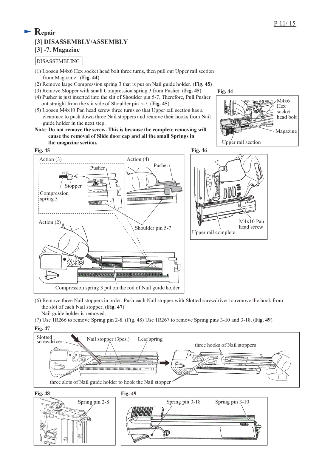
(1)Loosen M4x6 Hex socket head bolt three turns, then pull out Upper rail section from Magazine . (Fig. 44)
(2)Remove large Compression spring 3 that is put on Nail guide holder. (Fig. 45)
(3)Remove Stopper with small Compression spring 3 from Pusher. (Fig. 45)
(4)Pusher is just inserted into the slit of Shoulder pin
(5)Loosen M4x10 Pan head screw three turns so that Upper rail section has a clearance to push down three Nail stoppers and remove their hooks from Nail guide holder in the next step.
Note: Do not remove the screw. This is because the complete removing will cause the removal of Slide door cap and all the small Springs in the magazine section.
Fig. 45 | Fig. 46 |
Fig. 44
M4x6 |
Hex |
socket |
head bolt |
Magazine |
Upper rail section |
Action (3) |
| Action (4) |
|
| Pusher | Pusher |
|
|
|
| |
Stopper |
|
|
|
Compression |
|
|
|
spring 3 |
|
|
|
Action (2) |
|
| M4x10 Pan |
|
| Shoulder pin | head screw |
|
|
| Upper rail complete |
Compression spring 3 put on the rod of Nail guide holder |
| ||
(6)Remove three Nail stoppers in order. Push each Nail stopper with Slotted screwdriver to remove the hook from the slot of each Nail stopper. (Fig. 47)
Nail guide holder is removed.
(7)Use 1R266 to remove Spring pin
Fig. 47
Slotted | Nail stopper (3pcs.) | Leaf spring |
|
screwdriver |
| ||
| three hooks of Nail stoppers | ||
|
| ||
three slots of Nail guide holder to hook the Nail stopper |
| ||
Fig. 48 | Fig. 49 |
|
|
| Spring pin | Spring pin | Spring pin |