P 14/ 15
 Wiring diagram
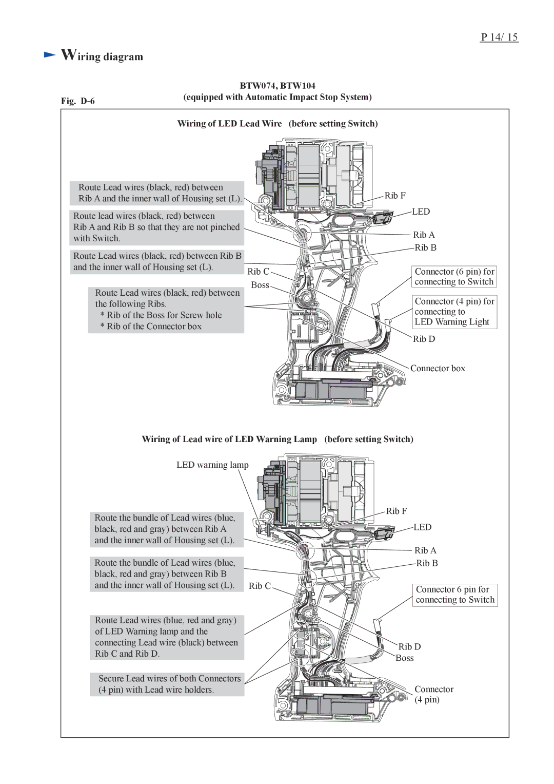
| BTW074, BTW104 | ||||||||||||||||||||||||||
Fig. | (equipped with Automatic Impact Stop System) | ||||||||||||||||||||||||||
|
|
|
|
|
|
|
|
|
|
|
|
|
|
|
|
|
|
|
|
|
|
|
|
|
|
| |
|
|
|
|
|
|
|
|
|
|
|
|
|
|
|
|
|
|
|
|
|
|
|
|
|
|
|
|
| Wiring of LED Lead Wire (before setting Switch) | ||||||||||||||||||||||||||
|
|
|
|
|
|
|
|
|
|
|
|
|
|
|
|
|
|
|
|
|
|
|
|
|
|
|
|
|
|
|
|
|
|
|
|
|
|
|
|
|
|
|
|
|
|
|
|
|
|
|
|
|
|
|
|
|
|
|
|
|
|
|
|
|
|
|
|
|
|
|
|
|
|
|
|
|
|
|
|
|
|
|
|
|
|
|
|
|
|
|
|
|
|
|
|
|
|
|
|
|
|
|
|
|
|
|
|
|
|
|
|
|
|
|
|
|
|
|
|
|
|
|
|
|
|
|
|
|
|
|
|
|
|
|
|
|
|
|
|
|
|
|
|
|
|
|
|
|
|
|
|
|
|
|
|
|
|
|
|
|
|
|
|
|
|
|
|
Route Lead wires (black, red) between
Rib A and the inner wall of Housing set (L).
Route lead wires (black, red) between
Rib A and Rib B so that they are not pinched with Switch.
Route Lead wires (black, red) between Rib B and the inner wall of Housing set (L).
Route Lead wires (black, red) between the following Ribs.
*Rib of the Boss for Screw hole
*Rib of the Connector box
| Rib F |
| LED |
| Rib A |
| Rib B |
Rib C | Connector (6 pin) for |
Boss | connecting to Switch |
| |
| Connector (4 pin) for |
| connecting to |
| LED Warning Light |
| Rib D |
![]()
![]()
![]()
![]()
![]()
![]()
![]()
![]()
![]()
![]()
![]()
![]()
![]()
![]()
![]()
![]()
![]()
![]()
![]() Connector box
Connector box
Wiring of Lead wire of LED Warning Lamp (before setting Switch)
LED warning lamp
Route the bundle of Lead wires (blue, black, red and gray) between Rib A and the inner wall of Housing set (L).
Route the bundle of Lead wires (blue, |
|
black, red and gray) between Rib B |
|
and the inner wall of Housing set (L). | Rib C |
|
|
Route Lead wires (blue, red and gray) |
|
of LED Warning lamp and the |
|
connecting Lead wire (black) between |
|
Rib C and Rib D. |
|
|
|
Secure Lead wires of both Connectors |
|
(4 pin) with Lead wire holders. |
|
Rib F
LED
![]()
![]()
![]()
![]() Rib A
Rib A
Rib B
Connector 6 pin for
![]() connecting to Switch
connecting to Switch
Rib D
Boss
Connector (4 pin)
