P 9/ 15
 Repair
[3]DISASSEMBLY/ASSEMBLY
[3]-5. Hammer section
DISASSEMBLING
(1)Loosen four M4x22 Pan head screws and separate Hammer case complete from Housing set. See the drawing on the upper left in Fig. 3.
(2)Remove Hammer section from Housing set. See Fig. 15.
Fig. 15
Hammer section |
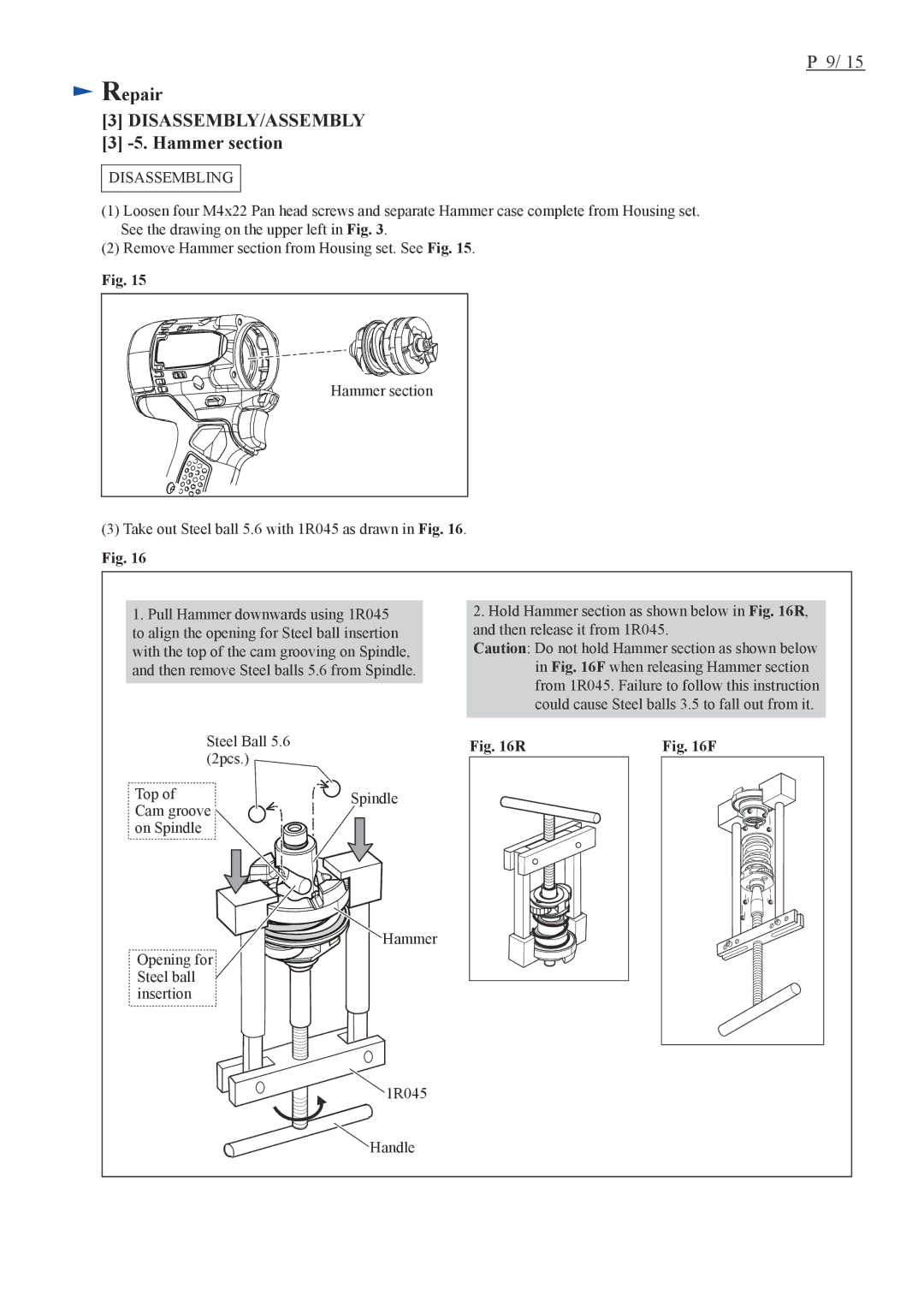
(3)Take out Steel ball 5.6 with 1R045 as drawn in Fig. 16.
Fig. 16
1.Pull Hammer downwards using 1R045 to align the opening for Steel ball insertion with the top of the cam grooving on Spindle, and then remove Steel balls 5.6 from Spindle.
2.Hold Hammer section as shown below in Fig. 16R, and then release it from 1R045.
Caution: Do not hold Hammer section as shown below in Fig. 16F when releasing Hammer section from 1R045. Failure to follow this instruction could cause Steel balls 3.5 to fall out from it.
Steel Ball 5.6 | Fig. 16R | Fig. 16F |
(2pcs.) |
|
|
Top of | Spindle |
|
Cam groove |
|
|
on Spindle |
|
|
![]() Hammer
Hammer
Opening for Steel ball
insertion
![]() 1R045
1R045
![]()
![]() Handle
Handle