P 5/ 15
 Repair
[3]DISASSEMBLY/ASSEMBLY
[3]-2. Armature (cont.)
DISASSEMBLING
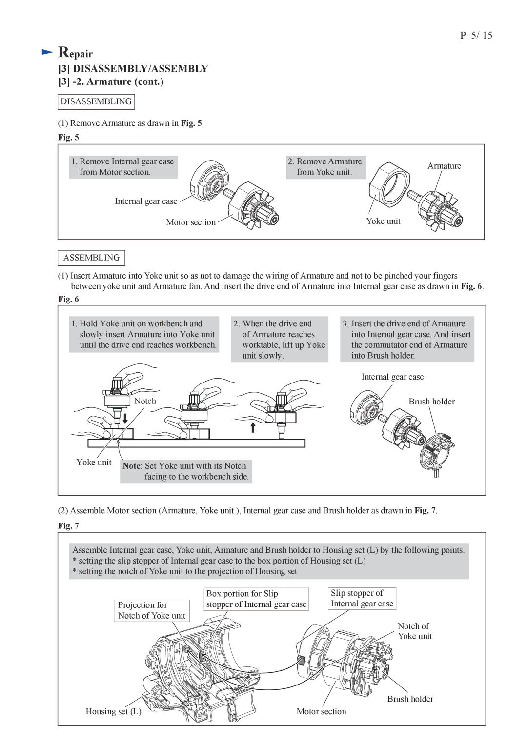
(1)Remove Armature as drawn in Fig. 5.
Fig. 5
1. Remove Internal gear case from Motor section.
Internal gear case ![]()
![]()
![]()
![]()
Motor section ![]()
2. Remove Armature | Armature | |
from Yoke unit. | ||
|
Yoke unit
ASSEMBLING
(1)Insert Armature into Yoke unit so as not to damage the wiring of Armature and not to be pinched your fingers between yoke unit and Armature fan. And insert the drive end of Armature into Internal gear case as drawn in Fig. 6.
Fig. 6
1. Hold Yoke unit on workbench and |
| 2. When the drive end | ||||||||||||||||||
slowly insert Armature into Yoke unit |
| of Armature reaches | ||||||||||||||||||
until the drive end reaches workbench. |
| worktable, lift up Yoke | ||||||||||||||||||
|
|
|
|
|
|
|
|
|
|
|
|
|
|
|
|
|
|
|
| unit slowly. |
|
|
|
|
|
|
|
|
|
|
|
|
|
|
|
|
|
|
| ||
|
|
|
|
|
|
|
|
|
|
|
|
|
|
|
|
|
|
|
|
|
|
|
|
|
|
|
|
|
|
|
|
|
|
|
|
|
|
|
|
|
|
Notch
3.Insert the drive end of Armature into Internal gear case. And insert the commutator end of Armature into Brush holder.
Internal gear case
Brush holder
Yoke unit |
| |
Note: Set Yoke unit with its Notch | ||
| ||
| facing to the workbench side. | |
|
|
(2)Assemble Motor section (Armature, Yoke unit ), Internal gear case and Brush holder as drawn in Fig. 7.
Fig. 7
Assemble Internal gear case, Yoke unit, Armature and Brush holder to Housing set (L) by the following points.
*setting the slip stopper of Internal gear case to the box portion of Housing set (L)
*setting the notch of Yoke unit to the projection of Housing set
Projection for Notch of Yoke unit
Box portion for Slip stopper of Internal gear case
Slip stopper of
Internal gear case
Notch of
Yoke unit
| Brush holder |
Housing set (L) | Motor section |
