P 6/ 15
 Repair
[3]DISASSEMBLY/ASSEMBLY
[3]-2. Armature (cont.)
ASSEMBLING
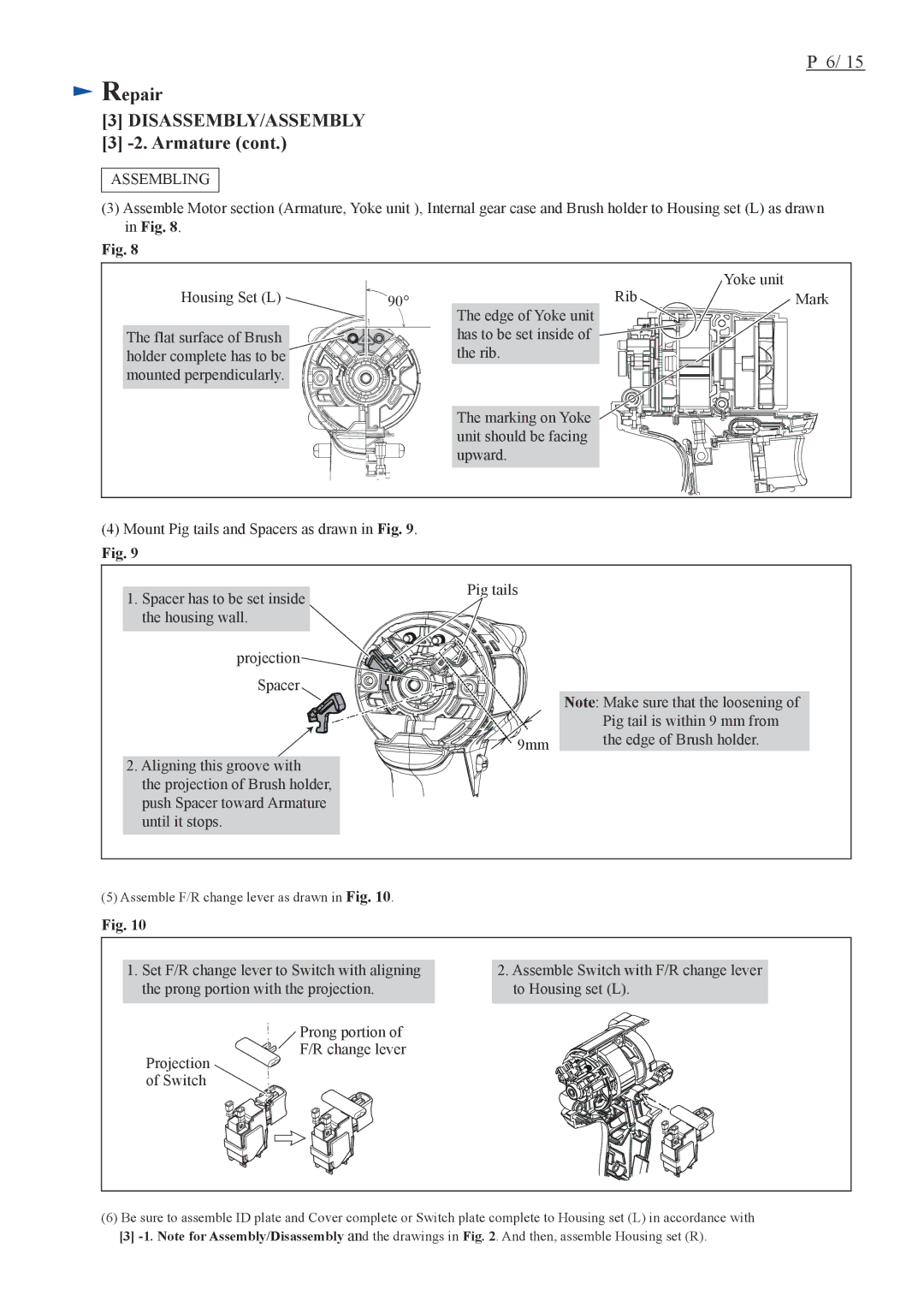
(3)Assemble Motor section (Armature, Yoke unit ), Internal gear case and Brush holder to Housing set (L) as drawn in Fig. 8.
Fig. 8
Housing Set (L)
The flat surface of Brush holder complete has to be mounted perpendicularly.
| Rib | Yoke unit |
90° | Mark | |
| The edge of Yoke unit |
|
| has to be set inside of |
|
| the rib. |
|
The marking on Yoke unit should be facing upward.
(4)Mount Pig tails and Spacers as drawn in Fig. 9.
Fig. 9
1.Spacer has to be set inside the housing wall.
projection Spacer
2.Aligning this groove with
the projection of Brush holder, push Spacer toward Armature until it stops.
Pig tails
| Note: Make sure that the loosening of |
| Pig tail is within 9 mm from |
9mm | the edge of Brush holder. |
|
(5)Assemble F/R change lever as drawn in Fig. 10.
Fig. 10
1.Set F/R change lever to Switch with aligning the prong portion with the projection.
2.Assemble Switch with F/R change lever to Housing set (L).
Projection of Switch
Prong portion of F/R change lever
(6)Be sure to assemble ID plate and Cover complete or Switch plate complete to Housing set (L) in accordance with
[3]
