P 15/ 15
 Wiring diagram
| BTW074, BTW104 |
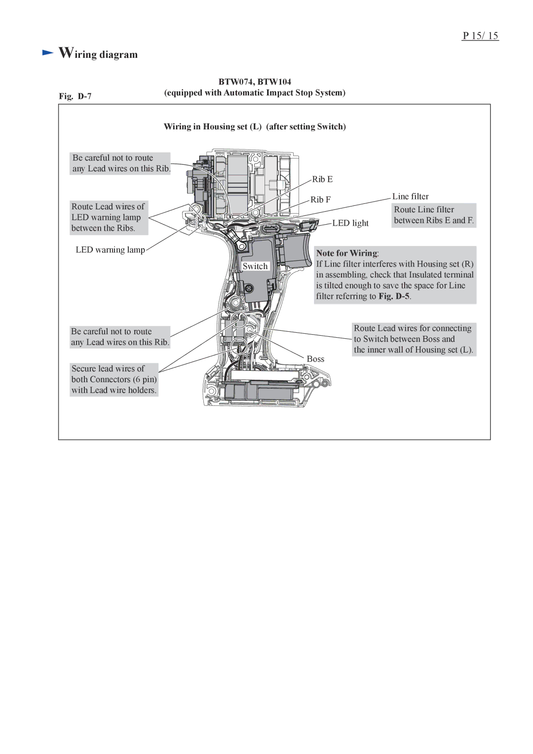
Fig. | (equipped with Automatic Impact Stop System) |
| |
|
|
| Wiring in Housing set (L) (after setting Switch) |
Be careful not to route
any Lead wires on this Rib.
Route Lead wires of LED warning lamp between the Ribs.
LED warning lamp
| Rib E |
|
| Rib F | Line filter |
| Route Line filter | |
|
| |
| LED light | between Ribs E and F. |
| Note for Wiring: |
|
Switch | If Line filter interferes with Housing set (R) | |
| in assembling, check that Insulated terminal | |
| is tilted enough to save the space for Line | |
| filter referring to Fig. | |
Be careful not to route
any Lead wires on this Rib.
Secure lead wires of both Connectors (6 pin) with Lead wire holders.
Boss |
Route Lead wires for connecting to Switch between Boss and the inner wall of Housing set (L).
