P 7/12
 Circuit diagram
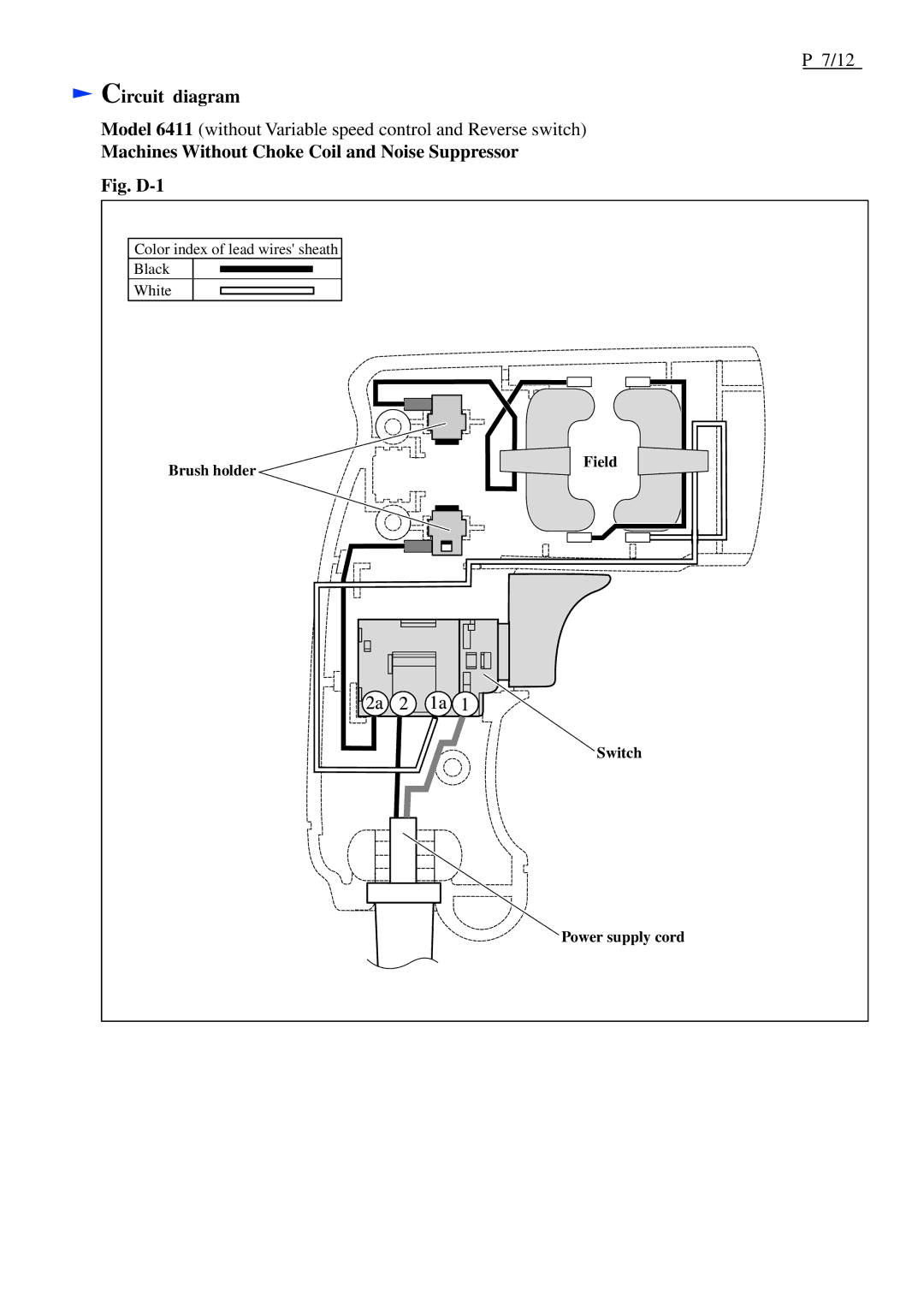
Model 6411 (without Variable speed control and Reverse switch)
Machines Without Choke Coil and Noise Suppressor
Fig. |
|
Color index of lead wires' sheath |
|
Black |
|
White |
|
Brush holder | Field |
| |
| Switch |
| Power supply cord |
P 7/12
Model 6411 (without Variable speed control and Reverse switch)
Fig. |
|
Color index of lead wires' sheath |
|
Black |
|
White |
|
Brush holder | Field |
| |
| Switch |
| Power supply cord |