P 8/12
 Wiring diagram
Model 6411 (without Variable speed control and Reverse switch)
Machines Without Choke Coil
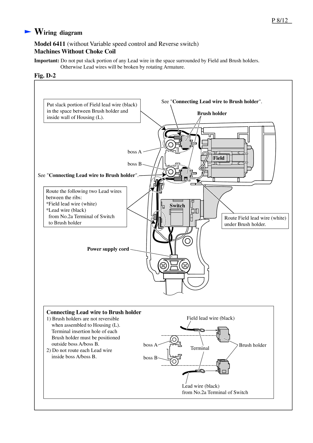
Important: Do not put slack portion of any Lead wire in the space surrounded by Field and Brush holders. Otherwise Lead wires will be broken by rotating Armature.
Fig. D-2
Put slack portion of Field lead wire (black) in the space between Brush holder and inside wall of Housing (L).
See "Connecting Lead wire to Brush holder".
Brush holder
boss A ![]()
boss B ![]()
See "Connecting Lead wire to Brush holder".![]()
Route the following two Lead wires |
| |
between the ribs: |
| |
*Field lead wire (white) | Switch | |
*Lead wire (black) | ||
| ||
from No.2a Terminal of Switch |
| |
to Brush holder |
|
![]() Field
Field
Route Field lead wire (white) under Brush holder.
Power supply cord
Connecting Lead wire to Brush holder
1) Brush holders are not reversible |
when assembled to Housing (L). |
Terminal insertion hole of each |
Brush holder must be positioned |
Field lead wire (black)
outside boss A/boss B. |
2) Do not route each Lead wire |
inside boss A/boss B. |
boss A![]()
boss B![]()
![]()
Terminal
Brush holder
Lead wire (black)
from No.2a Terminal of Switch