P 5/12
 Repair
[3]DISASSEMBLY/ASSEMBLY
[3]-2. Gear Section (cont.)
ASSEMBLING
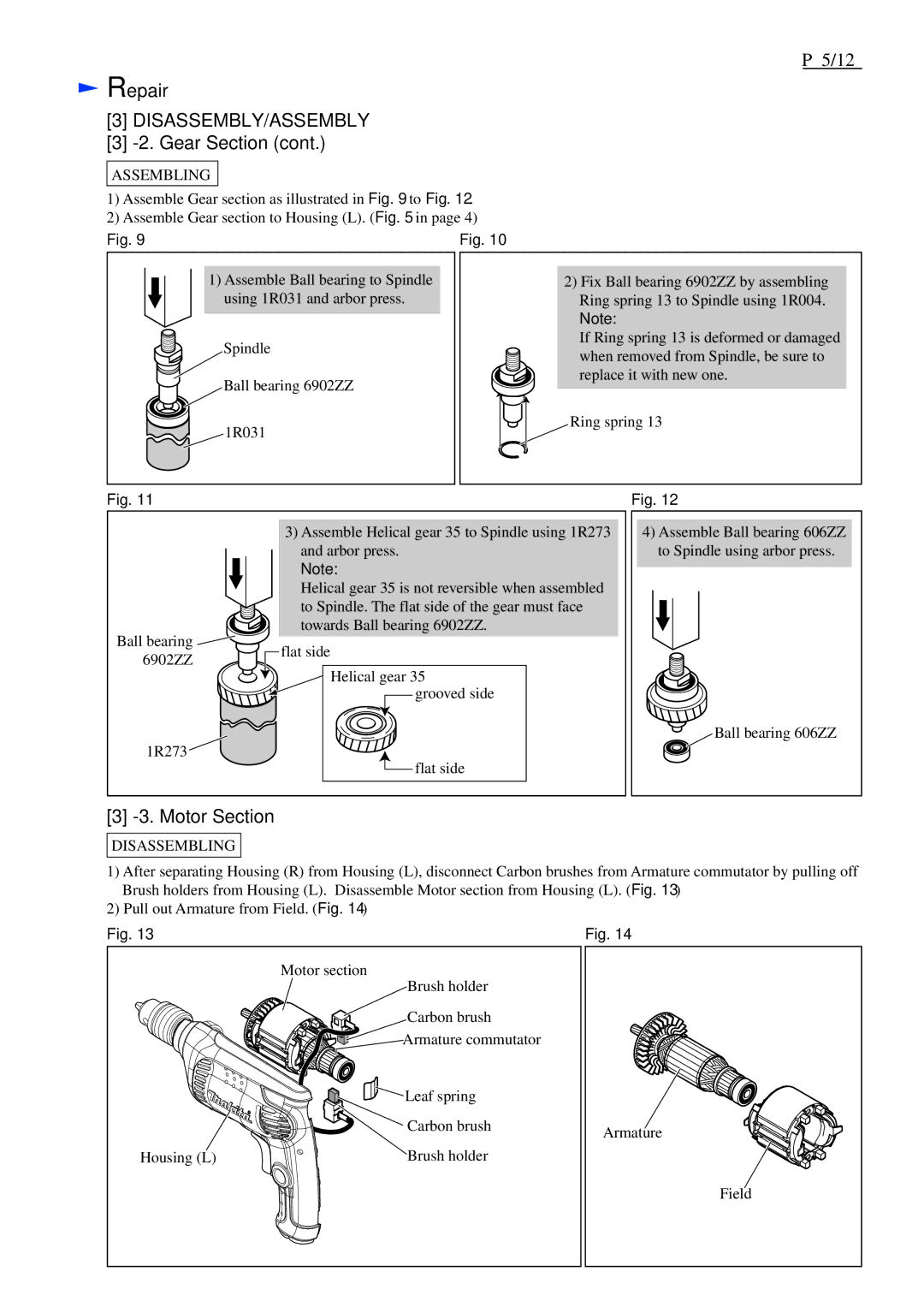
1)Assemble Gear section as illustrated in Fig. 9 to Fig. 12.
2)Assemble Gear section to Housing (L). (Fig. 5 in page 4)
Fig. 9
1)Assemble Ball bearing to Spindle using 1R031 and arbor press.
Spindle
Ball bearing 6902ZZ
1R031
Fig. 10
2) Fix Ball bearing 6902ZZ by assembling Ring spring 13 to Spindle using 1R004.
Note:
If Ring spring 13 is deformed or damaged when removed from Spindle, be sure to replace it with new one.
Ring spring 13
Fig. 11
3)Assemble Helical gear 35 to Spindle using 1R273 and arbor press.
Note:
Helical gear 35 is not reversible when assembled
to Spindle. The flat side of the gear must face
towards Ball bearing 6902ZZ.
Ball bearing ![]()
Fig. 12
4)Assemble Ball bearing 606ZZ to Spindle using arbor press.
6902ZZ
![]()
![]() flat side
flat side
Helical gear 35 grooved side
Ball bearing 606ZZ
1R273
![]() flat side
flat side
[3] -3. Motor Section
DISASSEMBLING
1)After separating Housing (R) from Housing (L), disconnect Carbon brushes from Armature commutator by pulling off Brush holders from Housing (L). Disassemble Motor section from Housing (L). (Fig. 13)
2)Pull out Armature from Field. (Fig. 14)
Fig. 13 | Fig. 14 |
| Motor section |
|
| Brush holder |
|
| Carbon brush |
|
| Armature commutator |
|
| Leaf spring |
|
| Carbon brush | Armature |
|
| |
Housing (L) | Brush holder |
|
|
| Field |
