ESU EROFE B P F O E MAN
SETUP
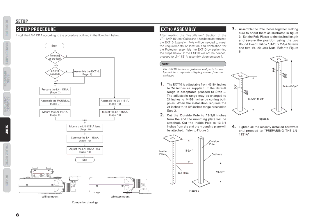
SETUP PROCEDURE
Install the
EXT10 ASSEMBLY
After reading the “Installation” Section of the
3. Assemble the Pole Pieces together making sure to orient them as illustrated in figure
3. Set the Pole Pieces to the desired length |
and secure the position using the two |
Round Head Philips |
STRA CI SAB AREPO NOI
Start
Mounting Y on the floor?
![]() N
N
EXT10 Y needed?
Assemble the EXT10.
(Page. 6)
the requirements of location and ventilation for the Projector, assemble the EXT10 by performing the steps below. If the EXT10 will not be needed, proceed to
Note:
The EXT10 hardware, fasteners and parts list are located in a separate shipping carton from the projector.
and two 1/4- 20 Lock Nuts. Refer to Figure |
6. |
T
N
1. The EXT10 is adjustable from
24 to
VDEARCELLNOART NOC ET O MER PUT AREPO N IO T AREP
Prepare the
(Page. 7)
|
|
|
|
|
|
|
Assemble the MOUNT20. |
|
|
| Assemble the | ||
(Page. 7) |
|
|
| (Page. 10) | ||
|
|
|
|
|
|
|
|
|
|
|
|
|
|
Mount the |
|
|
| Mount the | ||
(Page. 9) |
|
|
| (Page. 10) | ||
|
|
|
|
|
|
|
|
|
|
|
|
|
|
range is acceptable proceed to Step 3. The adjustable range may be changed to 24 inches to
2. Cut the Outside Pole to
Figure 6
EGS IN T OOHSEL BUORT O N IO T
SRE HT O
Mount the
Connect the
(Page. 10)
Adjust the
(Page. 11)
End
inches from the end the mounting plate will be attached. Refer to Figure 5.
Outside
![]() Pole
Pole
Inside | |
Pole | Cut Here |
|
|
|
|
|
| |||
Cut Here | ||||||||
|
|
|
|
|
|
|
|
|
|
|
|
|
|
|
|
|
|
|
|
|
|
|
|
|
|
|
4. Tighten all the recently installed hardware and proceed to “PREPARING THE LN- 11S1A”.
ceiling mount | tabletop mount |
Completion drawings
Figure 5
6