PRINCIPLES OF OPERATION
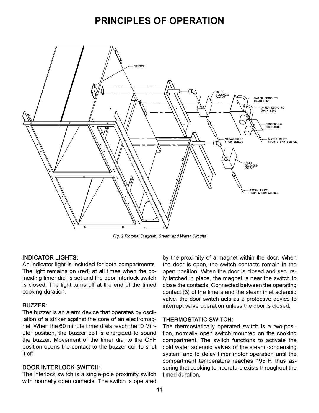
Fig. 2 Pictorial Diagram, Steam and Water Circuits
INDICATOR LIGHTS:by the proximity of a magnet within the door. When An indicator light is included for both compartments. the door is open, the switch contacts remain in the
The light remains on (red) at all times when the co- | open position. When the door is closed and secure- |
inciding timer dial is set and the door interlock switch | ly latched in place, the magnet is near the switch to |
is closed. The light turns off at the end of the timed | close the contacts. Connected between the operating |
cooking duration. | contact (3) of the timers and the steam inlet solenoid |
BUZZER: | valve, the door switch acts as a protective device to |
interrupt valve operation unless the door is closed. | |
The buzzer is an alarm device that operates by oscil- |
|
lation of a striker against the core of an electromag- | THERMOSTATIC SWITCH: |
net. When the 60 minute timer dials reach the “0 Min- | The thermostatically operated switch is a |
ute” position, the buzzer coil is energized to sound | tion, normally open switch mounted on the cooking |
the buzzer. Movement of the timer dial to the OFF | compartment. The switch functions to activate the |
position opens the contact to the buzzer coil to shut | cold water solenoid valves of the steam condensing |
it off. | system and to delay timer motor operation until the |
DOOR INTERLOCK SWITCH: | compartment temperature reaches 195°F, thus as- |
suring that cooking temperature exists throughout the | |
The interlock switch is a | timed duration. |
with normally open contacts. The switch is operated |
|
11
