Trigger Input (5V–24V DC)
If you have an external source component (such as a processor or a receiver) with built in trigger controls, you may wish to turn the subwoofer on and off with this source. Connect a cable from the control component to this input and set the Mode switch on the top panel to 'Auto (Trigger)'. Although this technology is commonly referred to as a 12V trigger, your subwoofer will respond to any signal between
Left In / Right In (Balanced XLR)
Connect from the
LFE In (Balanced XLR)
Connect from the LFE Out (or Sub Out) on your A/V processor. The setting for the
Left In / Right In (Line Level)
Connect from the
LFE In / Multi In (Line Level)
Connect from the LFE Out (Sub Out) on your A/V processor. The setting for the
If you are daisy chaining multiple identical subwoofers, you will use this input to connect from Multi Out on the controlling subwoofer.
Multi Out
If you are daisy chaining multiple subwoofers this output is used to connect and control additional subwoofers.
Left In / Right In (Speaker Level)
This set of inputs provides a place to connect the subwoofer using standard speaker cable. To use these connections the speaker cable should be terminated using banana style plugs. The settings for the
Break-In
Our custom made woofers require approximately 50 hours of
AC Power Connection
WARNING! The power cord should not be installed, removed, or left detached from the subwoofer while the other end is connected to an AC power source.
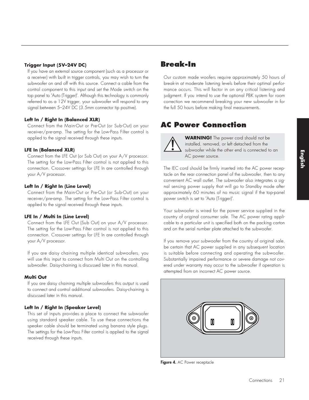
The IEC cord should be firmly inserted into the AC power recep- tacle on the rear connection panel of the subwoofer, then to any convenient AC wall outlet. The subwoofer also integrates a sig- nal sensing power supply that will go to Standby mode after approximately 60 minutes of no music signal if the
Your subwoofer is wired for the power service supplied in the country of original consumer sale. The AC power rating appli- cable to a particular unit is specified both on the packing carton and on the serial number plate attached to the subwoofer.
If you remove your subwoofer from the country of original sale, be certain that AC power supplied in any subsequent location is suitable before connecting and operating the subwoofer. Substantially impaired performance or severe damage not cov- ered under warranty may occur to the subwoofer if operation is attempted from an incorrect AC power source.
Figure 4. AC Power receptacle
English
Connections 21