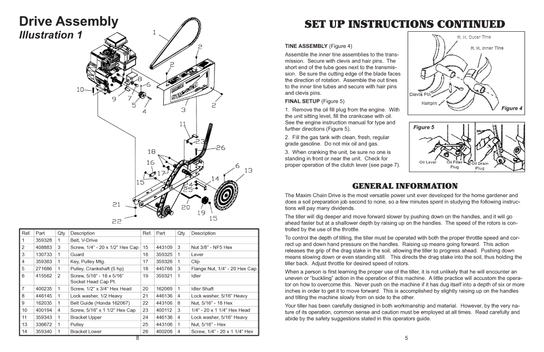
Drive Assembly
Illustration 1
SET UP INSTRUCTIONS CONTINUED
TINE ASSEMBLY (Figure 4)
Assemble the inner tine assemblies to the trans- mission. Secure with clevis and hair pins. The short end of the tube goes next to the transmis- sion. Be sure the cutting edge of the blade faces the direction of rotation. Assemble the out tines to the inner tine tubes and secure with hair pins and clevis pins.
FINAL SETUP (Figure 5)
1.Remove the oil fill plug from the engine. With the unit sitting level, fill the crankcase with oil. See the engine instruction manual for type and further directions (Figure 5).
2.Fill the gas tank with clean, fresh, regular grade gasoline. Do not mix oil and gas.
3.When cranking the unit, be sure no one is standing in front or near the unit. Check for proper operation of the clutch lever (see page 7).
Figure 4
Figure 5
| Ref. | Part | Qty | Description | Ref. | Part | Qty | Description |
|
|
|
|
|
|
|
|
|
| 1 | 359328 | 1 | Belt, |
|
|
|
|
|
|
|
|
|
|
|
|
|
| 2 | 408883 | 3 | Screw, 1/4” - 20 x 1/2” Hex Cap | 15 | 443109 | 3 | Nut 3/8” - NF5 Hex |
|
|
|
|
|
|
|
|
|
| 3 | 130733 | 1 | Guard | 16 | 359325 | 1 | Lever |
|
|
|
|
|
|
|
|
|
| 4 | 359383 | 1 | Key, Pulley Mtg. | 17 | 359326 | 1 | Clip |
|
|
|
|
|
|
|
|
|
| 5 | 271686 | 1 | Pulley, Crankshaft (5 hp) | 18 | 445768 | 3 | Flange Nut, 1/4” - 20 Hex Cap |
|
|
|
|
|
|
|
|
|
| 6 | 415562 | 2 | Screw, 5/16” - 18 x 5/16” | 19 | 359321 | 1 | Idler |
|
|
|
| Socket Head Cap Pt. |
|
|
|
|
|
|
|
|
|
|
|
|
|
| 7 | 400235 | 1 | Screw, 1/2” x 3/4” Hex Head | 20 | 162069 | 1 | Idler Shaft |
|
|
|
|
|
|
|
|
|
| 8 | 446145 | 1 | Lock washer, 1/2 Heavy | 21 | 446136 | 4 | Lock washer, 5/16” Heavy |
|
|
|
|
|
|
|
|
|
| 9 | 162035 | 1 | Belt Guide (Honda 162067) | 22 | 443106 | 8 | Nut, 5/16” - 18 Hex |
|
|
|
|
|
|
|
|
|
| 10 | 400194 | 4 | Screw, 5/16” x 1 1/2” Hex Cap | 23 | 400112 | 3 | 1/4” - 20 x 1 1/4” Hex Head |
|
|
|
|
|
|
|
|
|
| 11 | 359343 | 1 | Bracket Upper | 24 | 446136 | 4 | Lock washer, 5/16” Heavy |
|
|
|
|
|
|
|
|
|
| 13 | 336672 | 1 | Pulley | 25 | 443106 | 1 | Nut, 5/16” - Hex |
|
|
|
|
|
|
|
|
|
| 14 | 359340 | 1 | Bracket Lower | 26 | 400208 | 4 | Screw, 1/4” - 20 x 1 1/4” Hex |
|
|
|
|
|
|
|
|
|
8
GENERAL INFORMATION
The Maxim Chain Drive is the most versatile power unit ever developed for the home gardener and does a soil preparation job second to none, so a few minutes spent in studying the following instruc- tions will pay many dividends.
The tiller will dig deeper and move forward slower by pushing down on the handles, and it will go ahead faster but at a shallower depth by raising up on the handles. The speed of the rotors is con- trolled by the use of the throttle.
To control the depth of tilling, the tiller must be operated with both the proper throttle speed and cor- rect up and down hand pressure on the handles. Raising up means going forward. This action releases the grip of the drag stake in the soil, allowing the tiller to progress ahead. Pushing down means slowing down or even standing still. This directs the drag stake into the soil, thus holding the tiller back. Adjust throttle for desired speed of rotors.
When a person is first learning the proper use of the tiller, it is not unlikely that he will encounter an uneven or “buckling” action in the operation of this machine. A little practice will accustom the opera- tor on how to overcome this. Never push on the machine if it has dug itself into a depth of six or more inches in order to get it to move forward. This is accomplished by slightly raising up on the handles and tilting the machine slowly from on side to the other.
Your tiller has been carefully designed in both workmanship and material. However, by the very na- ture of its operation, common sense and caution must be employed at all times. Read carefully and abide by the safety suggestions stated in this operators guide.
5