Retrieve message | |
Disable DSVD | |
n=1 | Enable DSVD |
Set transmission speeds | |
Start sequence response control | |
Data mode event message | |
Time | |
Telephone handset transaction tone | |
| control |
Start Voice View data mode | |
|
|
Section Four - S Registers
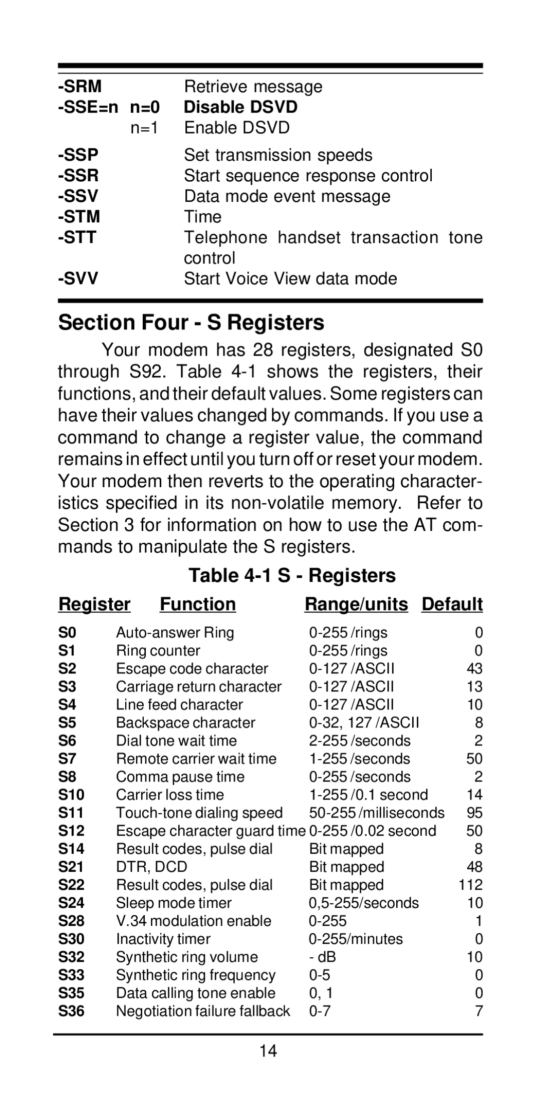
Your modem has 28 registers, designated S0 through S92. Table
Table 4-1 S - Registers
Register | Function | Range/units Default | |||
S0 | /rings | 0 | |||
S1 | Ring counter | /rings | 0 | ||
S2 | Escape code character | /ASCII | 43 | ||
S3 | Carriage return character | /ASCII | 13 | ||
S4 | Line feed character | /ASCII | 10 | ||
S5 | Backspace character | 8 | |||
S6 | Dial tone wait time | 2 | |||
S7 | Remote carrier wait time | 50 | |||
S8 | Comma pause time | 2 | |||
S10 | Carrier loss time | /0.1 second | 14 | ||
S11 | 95 | ||||
S12 | Escape character guard time | /0.02 second | 50 | ||
S14 | Result codes, pulse dial | Bit mapped | 8 | ||
S21 | DTR, DCD | Bit mapped | 48 | ||
S22 | Result codes, pulse dial | Bit mapped | 112 | ||
S24 | Sleep mode timer | 10 | |||
S28 | V.34 modulation enable |
| 1 | ||
S30 | Inactivity timer | 0 | |||
S32 | Synthetic ring volume | - dB |
| 10 | |
S33 | Synthetic ring frequency |
| 0 | ||
S35 | Data calling tone enable | 0, 1 |
| 0 | |
S36 | Negotiation failure fallback |
| 7 | ||
14
