Installation
The configuration of the following three jumpers controls the drive’s five modes of operation:
–CS – Cable Select
–DS – Drive Select
–CLJ– Cylinder Limitation Jumper
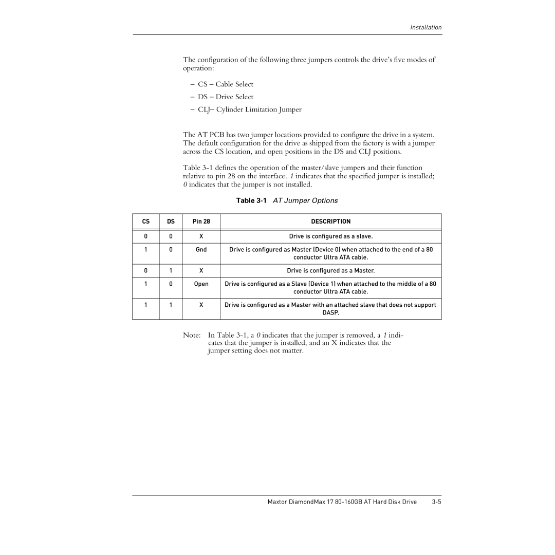
The AT PCB has two jumper locations provided to configure the drive in a system. The default configuration for the drive as shipped from the factory is with a jumper across the CS location, and open positions in the DS and CLJ positions.
Table
|
|
| Table |
|
|
|
|
CS | DS | Pin 28 | DESCRIPTION |
|
|
|
|
|
|
|
|
0 | 0 | X | Drive is configured as a slave. |
|
|
|
|
1 | 0 | Gnd | Drive is configured as Master (Device 0) when attached to the end of a 80 |
|
|
| conductor Ultra ATA cable. |
|
|
|
|
0 | 1 | X | Drive is configured as a Master. |
|
|
|
|
1 | 0 | Open | Drive is configured as a Slave (Device 1) when attached to the middle of a 80 |
|
|
| conductor Ultra ATA cable. |
|
|
|
|
1 | 1 | X | Drive is configured as a Master with an attached slave that does not support |
|
|
| DASP. |
|
|
|
|
Note: In Table
Maxtor DiamondMax 17 |
