Installation
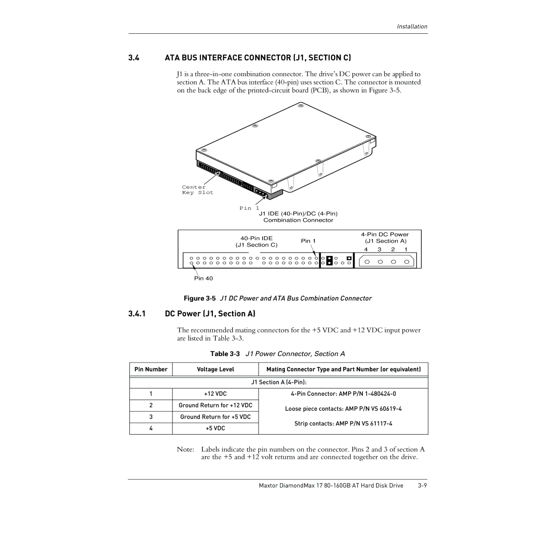
3.4ATA BUS INTERFACE CONNECTOR (J1, SECTION C)
J1 is a
Center
Key Slot
Pin 1
J1 IDE
Combination Connector
| ||||||
Pin 1 | (J1 Section A) | |||||
(J1 Section C) | ||||||
| 4 | 3 | 2 | 1 | ||
|
| |||||
Pin 40
Figure 3-5 J1 DC Power and ATA Bus Combination Connector
3.4.1DC Power (J1, Section A)
The recommended mating connectors for the +5 VDC and +12 VDC input power are listed in Table
Table 3-3 J1 Power Connector, Section A
Pin Number | Voltage Level |
| Mating Connector Type and Part Number (or equivalent) |
|
|
|
|
|
|
| |
|
| J1 Section A | |
|
|
|
|
1 | +12 VDC |
| |
|
|
| |
2 | Ground Return for +12 VDC | Loose piece contacts: AMP P/N VS | |
|
|
| |
3 | Ground Return for +5 VDC |
| Strip contacts: AMP P/N VS |
|
|
| |
4 | +5 VDC |
| |
|
| ||
|
|
|
|
Note: Labels indicate the pin numbers on the connector. Pins 2 and 3 of section A are the +5 and +12 volt returns and are connected together on the drive.
Maxtor DiamondMax 17 |