
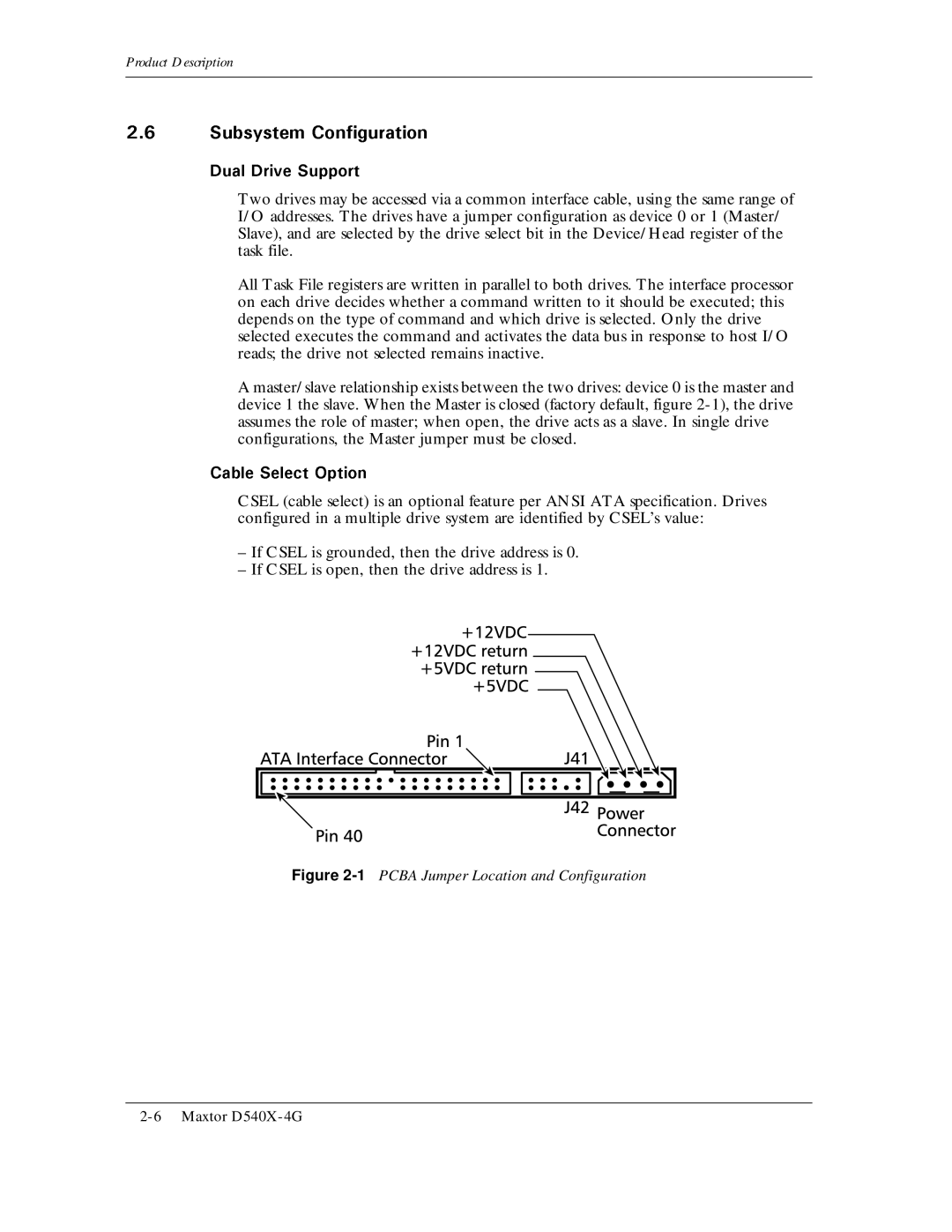
D540X-4G specifications
The Maxtor D540X-4G, introduced in the early 2000s, is a notable hard disk drive that carved a niche in the consumer and business storage market. It is part of the D540X series, known for its reliability and substantial storage capacity for its time, boasting an impressive 4GB of storage.One of the standout features of the D540X-4G is its advanced ATA/100 interface, allowing for a high data transfer rate of up to 100 MB/s. This was a significant leap forward in performance, enabling faster access to data and improved system responsiveness. Unlike older interfaces, the ATA/100 significantly reduced bottlenecks, making it an ideal choice for users who required efficient data management.
The D540X-4G was built on a 5400 RPM spindle speed. While this wasn't as fast as some higher-end drives available at the time, it provided a balance between speed and thermal efficiency. The combination of its rotational speed and data density allowed for a commendable average seek time, which translated into quicker file access for everyday applications, such as word processing and spreadsheet management.
Another commendable attribute of the D540X-4G is its acoustic management technology, which ensured that the drive operated quietly, minimizing distraction in office environments or home setups. This was particularly beneficial for users who needed to maintain a serene working atmosphere.
In terms of durability, the D540X-4G featured a robust design with built-in shock protection. This characteristic offered an additional layer of safety for data integrity, especially vital in portable systems where exposure to movement is frequent. Maxtor also placed a focus on providing error-correction capabilities, which further enhanced data reliability.
The D540X-4G utilized a halogen-free design in its manufacturing process, reflecting an early commitment to environmental considerations, which would become increasingly important in the years to follow.
Overall, the Maxtor D540X-4G hard drive highlighted the advancements in storage technology of the time, combining ample capacity, improved speed, and reliability in a user-friendly package. It appealed to a broad spectrum of users, from everyday home computing to small business applications, making it a valuable player in the computing landscape during its era.