Maytag 110 installation instructions Servicing

Models: 110

1 36
Download 36 pages 10.49 Kb
Page 30
Image 30
Servicing

SERVICING - WARNING

Disconnect from electricity and gas before servicing. Check appliance is safe when you have finished.

Servicing

BEFORE SERVICING ANY GAS CARRYING COMPONENTS. TURN OFF THE GAS SUPPLY

Check the appliance is gas sound after completion of service. When checking for gas leaks do not use washing up liquid - this can corrode. Use a product specifically manufactured for leak detection.

Do not use re-conditioned or unauthorised gas controls.

Disconnect from the electricity supply before commencing servicing, particularly before removing any of the following: - control panel, side panels, hotplate tray or any electrical components or covers.

Before electrical re-connection, check that the appliance is electrically safe.

Note - References to LH and RH oven apply as viewed from the front.

1 To Remove the Control Panel

Disconnect the appliance from the electricity supply.

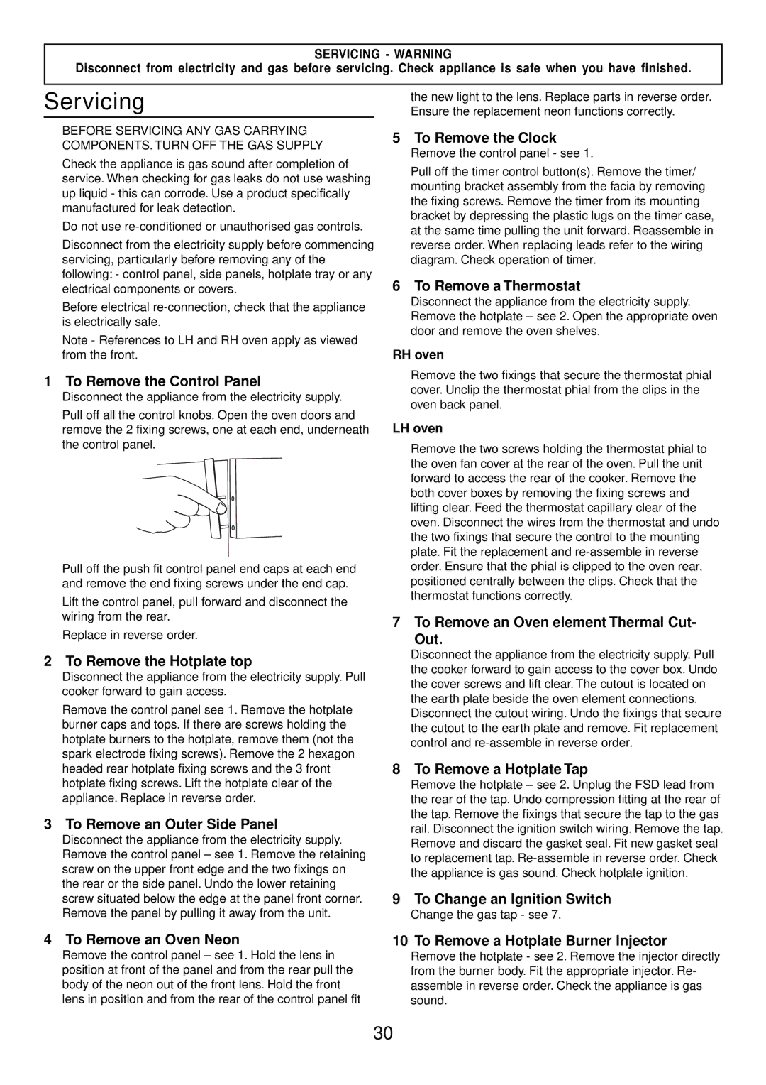
Pull off all the control knobs. Open the oven doors and remove the 2 fixing screws, one at each end, underneath the control panel.

Pull off the push fit control panel end caps at each end and remove the end fixing screws under the end cap.

Lift the control panel, pull forward and disconnect the wiring from the rear.

Replace in reverse order.

2 To Remove the Hotplate top

Disconnect the appliance from the electricity supply. Pull cooker forward to gain access.

Remove the control panel see 1. Remove the hotplate burner caps and tops. If there are screws holding the hotplate burners to the hotplate, remove them (not the spark electrode fixing screws). Remove the 2 hexagon headed rear hotplate fixing screws and the 3 front hotplate fixing screws. Lift the hotplate clear of the appliance. Replace in reverse order.

3 To Remove an Outer Side Panel

Disconnect the appliance from the electricity supply. Remove the control panel – see 1. Remove the retaining screw on the upper front edge and the two fixings on the rear or the side panel. Undo the lower retaining screw situated below the edge at the panel front corner. Remove the panel by pulling it away from the unit.

4 To Remove an Oven Neon

Remove the control panel – see 1. Hold the lens in position at front of the panel and from the rear pull the body of the neon out of the front lens. Hold the front lens in position and from the rear of the control panel fit

the new light to the lens. Replace parts in reverse order. Ensure the replacement neon functions correctly.

5 To Remove the Clock

Remove the control panel - see 1.

Pull off the timer control button(s). Remove the timer/ mounting bracket assembly from the facia by removing the fixing screws. Remove the timer from its mounting bracket by depressing the plastic lugs on the timer case, at the same time pulling the unit forward. Reassemble in reverse order. When replacing leads refer to the wiring diagram. Check operation of timer.

6 To Remove a Thermostat

Disconnect the appliance from the electricity supply. Remove the hotplate – see 2. Open the appropriate oven door and remove the oven shelves.

RH oven

Remove the two fixings that secure the thermostat phial cover. Unclip the thermostat phial from the clips in the oven back panel.

LH oven

Remove the two screws holding the thermostat phial to the oven fan cover at the rear of the oven. Pull the unit forward to access the rear of the cooker. Remove the both cover boxes by removing the fixing screws and lifting clear. Feed the thermostat capillary clear of the oven. Disconnect the wires from the thermostat and undo the two fixings that secure the control to the mounting plate. Fit the replacement and re-assemble in reverse order. Ensure that the phial is clipped to the oven rear, positioned centrally between the clips. Check that the thermostat functions correctly.

7 To Remove an Oven element Thermal Cut- Out.

Disconnect the appliance from the electricity supply. Pull the cooker forward to gain access to the cover box. Undo the cover screws and lift clear. The cutout is located on the earth plate beside the oven element connections. Disconnect the cutout wiring. Undo the fixings that secure the cutout to the earth plate and remove. Fit replacement control and re-assemble in reverse order.

8 To Remove a Hotplate Tap

Remove the hotplate – see 2. Unplug the FSD lead from the rear of the tap. Undo compression fitting at the rear of the tap. Remove the fixings that secure the tap to the gas rail. Disconnect the ignition switch wiring. Remove the tap. Remove and discard the gasket seal. Fit new gasket seal to replacement tap. Re-assemble in reverse order. Check the appliance is gas sound. Check hotplate ignition.

9 To Change an Ignition Switch

Change the gas tap - see 7.

10 To Remove a Hotplate Burner Injector

Remove the hotplate - see 2. Remove the injector directly from the burner body. Fit the appropriate injector. Re- assemble in reverse order. Check the appliance is gas sound.

30

Page 30
Image 30
Maytag 110 installation instructions Servicing