
9096336202, MCT3362VA, 966992201 specifications
The McCulloch 966992201, MCT3362VA, and 9096336202 represent a trio of high-quality outdoor power equipment designed to meet the needs of both professionals and DIY enthusiasts. McCulloch is renowned for its commitment to innovation, reliability, and performance, and these models uphold that reputation with varied features and technologies aimed at enhancing user experience.The McCulloch 966992201 is a robust chainsaw that stands out for its powerful engine and exceptional cutting capabilities. With a 50cc engine, it delivers high performance and efficiency, allowing users to tackle even the toughest wood cutting tasks with ease. The chainsaw features an automatic oiling system, ensuring the chain remains lubricated, which enhances durability and reduces maintenance needs. Additionally, its lightweight design ensures that users can maneuver the chainsaw comfortably, minimizing fatigue during extended use.
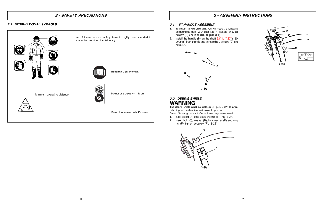
The MCT3362VA is a versatile multi-tool that offers a range of attachments for various gardening tasks, including trimming, edging, and pruning. This model features a powerful engine that ensures reliable performance for various attachments. Its easy-to-switch system allows users to interchange different tools effortlessly, making it an invaluable asset for both yard maintenance and extensive landscaping projects. The ergonomic design supports user comfort, and the adjustable handle increases versatility for multiple operating positions.
Lastly, the 9096336202 model is a high-performance leaf blower that efficiently clears debris and leaves, making it ideal for maintaining clean outdoor spaces. With a powerful air output, this blower can easily manage both light and heavy debris, enhancing cleanliness in gardens and yards. The ergonomic design and lightweight structure enhance maneuverability, while the variable speed settings allow users to adjust airflow according to their needs.
All three models incorporate McCulloch’s innovative technologies, designed to improve efficiency and ease of use. Features like their air purge system for easier starting, vibration-dampening mechanisms to reduce user fatigue, and advanced filtration systems for cleaner operation highlight the brand's focus on user-friendly designs. Collectively, the McCulloch 966992201, MCT3362VA, and 9096336202 represent a comprehensive range of solutions for outdoor maintenance, ensuring that users enjoy powerful performance and durability with every use. Whether you’re cutting, trimming, or cleaning, McCulloch provides the tools you need to get the job done effectively.