MT10 specifications
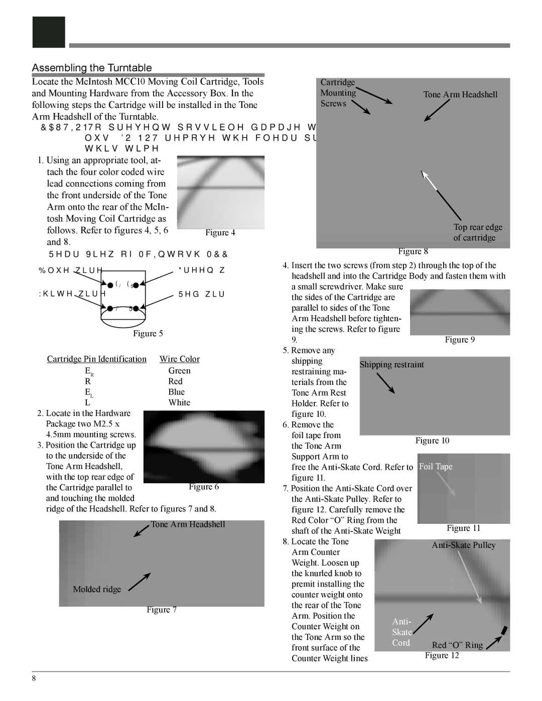
The McIntosh MT10 is a remarkable turntable that embodies the company's commitment to high fidelity and exceptional audio quality. As part of McIntosh's tradition of creating superior audio equipment, the MT10 offers audiophiles a blend of advanced technology and timeless design, perfect for both casual listeners and serious collectors.One of the standout features of the MT10 is its ingenious design. The turntable is constructed with a sleek, high-gloss finish and a sturdy chassis, ensuring minimal vibration and impressive stability during playback. This is paramount for preserving sound quality. The MT10 boasts a 10-inch, aluminum tonearm, which is precision-engineered to enhance tracking performance while minimizing distortion. This results in a rich, detailed sound that allows listeners to fully appreciate the nuances of their vinyl records.
At the heart of the MT10 is a highly accurate, low-noise synchronous AC motor that drives its precision machined platter. The platter itself is made from glass, a choice that contributes to the overall aesthetics while also delivering strong performance with excellent inertia and speed consistency. The turntable supports a range of speeds, including 33 1/3 and 45 RPM, making it versatile enough to handle any vinyl record.
Another key feature of the MT10 is its advanced isolation system. The turntable employs a unique suspension system designed to minimize external vibrations, further enhancing audio fidelity. This technology ensures that even within less-than-ideal environments, such as homes with foot traffic or neighboring noise, the playback remains crystal clear and free from unwanted interference.
Additionally, the MT10 is equipped with a state-of-the-art phono preamplifier, making it compatible with various audio systems without the need for external components. It features adjustable gain settings to match different cartridge outputs, providing flexibility for users to optimize their listening experience.
Aesthetically, the MT10 stands out with its iconic McIntosh design elements, including the signature black glass front panel and illuminated logo. This turntable not only performs exceptionally but also serves as a stunning centerpiece in any audio setup.
In summary, the McIntosh MT10 is a premium turntable that combines classic design with innovative technology. With its exceptional build quality, advanced isolation system, and precise playback capabilities, the MT10 is an ideal choice for anyone looking to elevate their vinyl listening experience to new heights. Whether an audiophile or a casual listener, the MT10 promises a superb sound experience steeped in the rich tradition of McIntosh audio excellence.

