Installing the |
Pin out – auxiliary DIO connector
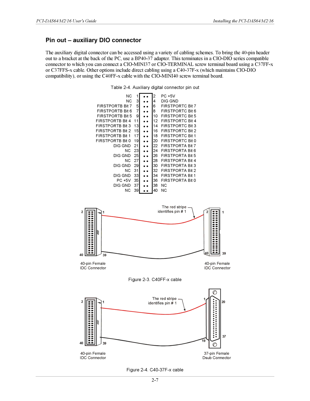
The auxiliary digital connector can be accessed using a variety of cabling schemes. To bring the
Table 2-4. Auxiliary digital connector pin out
|
|
|
| NC | 1 | • • |
|
|
|
| NC | 3 | • • |
|
|
|
| FIRSTPORTB Bit 7 | 5 | • • |
|
|
|
| FIRSTPORTB Bit 6 | 7 | • • |
|
|
|
| FIRSTPORTB Bit 5 | 9 | • • |
|
|
|
| FIRSTPORTB Bit 4 | 11 | • • |
|
|
|
| FIRSTPORTB Bit 3 | 13 | • • |
|
|
|
| FIRSTPORTB Bit 2 | 15 | • • |
|
|
|
| FIRSTPORTB Bit 1 | 17 | • • |
|
|
|
| FIRSTPORTB Bit 0 | 19 | • • |
|
|
|
| DIG GND | 21 | • • |
|
|
|
| NC | 23 | • • |
|
|
|
| DIG GND | 25 | • • |
|
|
|
| NC | 27 | • • |
|
|
|
| DIG GND | 29 | • • |
|
|
|
| NC | 31 | • • |
|
|
|
| DIG GND | 33 | • • |
|
|
|
| PC +5V | 35 | • • |
|
|
|
| DIG GND | 37 | • • |
|
|
|
| NC | 39 | • • |
2 |
|
|
| 1 |
|
|
|
|
|
| |||
|
|
|
|
|
|
|
|
|
|
|
|
|
|
|
|
|
|
|
|
|
|
|
|
|
|
|
|
|
|
|
|
|
|
|
|
|
|
|
|
|
|
|
|
|
|
|
|
|
|
|
|
|
|
|
|
|
|
|
|
|
|
|
|
|
|
|
|
|
|
|
|
|
|
|
|
|
|
|
|
|
|
|
|
|
|
|
|
|
|
|
|
|
|
|
|
|
|
|
|
|
|
|
|
|
|
|
|
|
|
|
|
|
|
|
|
|
|
|
2PC +5V
4 DIG GND
6 FIRSTPORTC Bit 7
8 FIRSTPORTC Bit 6
10 FIRSTPORTC Bit 5
12 FIRSTPORTC Bit 4
14 FIRSTPORTC Bit 3
16 FIRSTPORTC Bit 2
18 FIRSTPORTC Bit 1
20 FIRSTPORTC Bit 0
22 FIRSTPORTA Bit 7
24 FIRSTPORTA Bit 6
26 FIRSTPORTA Bit 5
28 FIRSTPORTA Bit 4
30 FIRSTPORTA Bit 3
32 FIRSTPORTA Bit 2
34 FIRSTPORTA Bit 1
36 FIRSTPORTA Bit 0
38 NC
40 NC
The red stripe |
|
|
identifies pin # 1 | 2 | 1 |
4039
39
IDC Connector | IDC Connector |
Figure 2-3. C40FF-x cable
2 |
|
|
| 1 | The red stripe | 1 |
|
|
| identifies pin # 1 |
| ||
|
|
|
| |||
|
|
|
|
|
|
|
|
|
|
|
|
|
|
|
|
|
|
|
|
|
|
|
|
|
|
|
|
|
|
|
|
|
|
|
|
|
|
|
|
|
|
|
|
|
|
|
|
|
|
|
|
|
|
|
|
|
|
|
|
|
|
|
|
|
|
|
|
|
|
|
|
|
|
|
|
|
|
|
|
|
|
|
|
|
|
|
|
|
|
|
|
|
|
|
|
|
|
|
|
|
|
|
|
|
40 |
|
|
| 39 | 19 |
|
|
| |||
|
|
|
|
20
37
IDC Connector | Dsub Connector |