Installing the |
19 ![]()
1
37
20
39 ![]()
![]() 40
40
Key 


![]() 1
1 ![]()
![]() 2
2
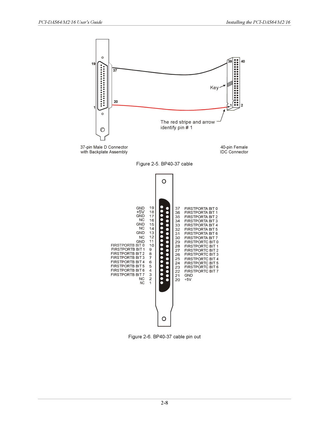
The red stripe and arrow  identify pin # 1
with Backplate Assembly | IDC Connector |
Figure 2-5. BP40-37 cable
GND
+5V
GND
NC
GND
NC
GND
NC
GND
FIRSTPORTB BIT 1 FIRSTPORTB BIT 2 FIRSTPORTB BIT 3 FIRSTPORTB BIT 4 FIRSTPORTB BIT 5 FIRSTPORTB BIT 6 FIRSTPORTB BIT 7
NC
FIRSTPORTA BIT 0 FIRSTPORTA BIT 1 FIRSTPORTA BIT 2 FIRSTPORTA BIT 3 FIRSTPORTA BIT 4 FIRSTPORTA BIT 5 FIRSTPORTA BIT 6 FIRSTPORTA BIT 7 FIRSTPORTC BIT 0 FIRSTPORTC BIT 1 FIRSTPORTC BIT 2 FIRSTPORTC BIT 3 FIRSTPORTC BIT 4 FIRSTPORTC BIT 5 FIRSTPORTC BIT 6 FIRSTPORTC BIT 7 GND
+5V