Installing the |
40-pin to 37-pin signal mapping
Signal mapping on the
Table 2-5. Signal mapping on the C40-37F-x and BP40-37F cables
|
| ||
Pin | Signal Name | Pin | Signal Name |
1 | INTERRUPT IN | 1 | INTERRUPT IN |
2 | +5V | 20 | +5V |
3 | INTERRUPT ENABLE | 2 | INTERRUPT ENABLE |
4 | GND | 21 | GND |
5 | Port B 7 | 3 | Port B 7 |
6 | Port C 7 | 22 | Port C 7 |
7 | Port B 6 | 4 | Port B 6 |
8 | Port C 6 | 23 | Port C 6 |
9 | Port B 5 | 5 | Port B 5 |
10 | Port C 5 | 24 | Port C 5 |
11 | Port B 4 | 6 | Port B 4 |
12 | Port C 4 | 25 | Port C 4 |
13 | Port B 3 | 7 | Port B 3 |
14 | Port C 3 | 26 | Port C 3 |
15 | Port B 2 | 8 | Port B 2 |
16 | Port C 2 | 27 | Port C 2 |
17 | Port B 1 | 9 | Port B 1 |
18 | Port C 1 | 28 | Port C 1 |
19 | Port B 0 | 10 | Port B 0 |
20 | Port C 0 | 29 | Port C 0 |
21 | GND | 11 | GND |
22 | Port A 7 | 30 | Port A 7 |
23 | N/C | 12 | N/C |
24 | Port A 6 | 31 | Port A 6 |
25 | GND | 13 | GND |
26 | Port A 5 | 32 | Port A 5 |
27 | N/C | 14 | N/C |
28 | Port A 4 | 33 | Port A 4 |
29 | GND | 15 | GND |
30 | Port A 3 | 34 | Port A 3 |
31 | N/C | 16 | N/C |
32 | Port A 2 | 35 | Port A 2 |
33 | GND | 17 | GND |
34 | Port A 1 | 36 | Port A 1 |
35 | +5V | 18 | +5V |
36 | Port A 0 | 37 | Port A 0 |
37 | GND | 19 | GND |
38 | N/C |
|
|
39 | N/C |
|
|
40 | N/C |
|
|
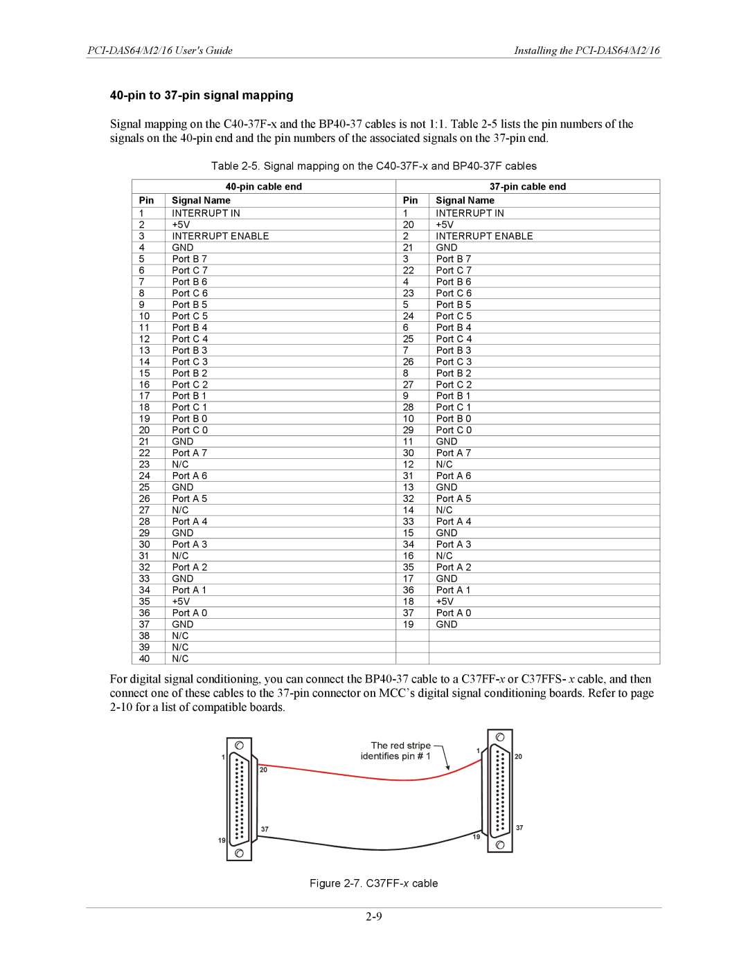
For digital signal conditioning, you can connect the
1 ![]()
20
The red stripe | 1 | |
identifies pin # 1 | ||
|
20
37 | 37 |
19 | 19 |
|